
Kirchhoff’s Loop Rule

Understanding Kirchhoff’s Loop Rule is essential for mastering circuit analysis in the AP Physics exam. This rule, along with Kirchhoff’s Junction Rule, is fundamental for analyzing complex electrical circuits. Below are detailed notes along with five examples to help you achieve a high score on your AP Physics exam.
Learning Objectives
For the AP Physics exam, you should learn how to apply Kirchhoff’s Loop Rule to analyze electric circuits. This includes understanding the principle of conservation of energy in electrical loops, calculating voltage drops and gains around a circuit loop, and using the rule to solve for unknown values such as current and voltage in complex circuits. Mastering this concept will enable you to approach circuit problems systematically and accurately, an essential skill for success on the exam.
Kirchhoff’s Loop Rule
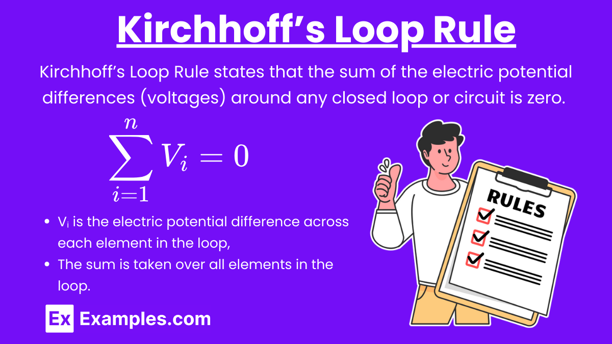
Kirchhoff’s Loop Rule: Kirchhoff’s Loop Rule, also known as Kirchhoff’s Voltage Law (KVL), states that the sum of the electric potential differences (voltages) around any closed loop or circuit is zero. This is a consequence of the conservation of energy.
Mathematical Expression
![\[ \sum_{i=1}^{n} V_i = 0 \]](https://www.examples.com/wp-content/ql-cache/quicklatex.com-6dd41c3bc707783134814aefba734f35_l3.svg "Rendered by QuickLaTeX.com")
where:
- Vᵢ is the electric potential difference across each element in the loop,
- The sum is taken over all elements in the loop.
Key Points
- The rule applies to any closed loop in a circuit.
- Voltage rises (due to sources like batteries) are considered positive.
- Voltage drops (due to resistors and other components) are considered negative.
Applying Kirchhoff’s Loop Rule
Steps
- Identify loops: Identify and label all the closed loops in the circuit.
- Assign directions: Assign a direction (clockwise or counterclockwise) to each loop.
- Apply the rule: Write the Kirchhoff’s Loop Rule equation for each loop, accounting for voltage rises and drops.
- Solve the equations: Solve the resulting system of equations to find unknown currents or voltages.
Example 1
Simple Series Circuit
Scenario: Consider a series circuit with a 12 V battery and two resistors, R₁ = 2Ω and R₂ = 4Ω. Find the current in the circuit.
Solution:
- Identify the loop: The entire series circuit is one loop.
- Assign direction: Assume a clockwise direction.
- Apply Kirchhoff’s Loop Rule:
![\[ 12V - I \cdot R_1 - I \cdot R_2 = 0 \]](https://www.examples.com/wp-content/ql-cache/quicklatex.com-d41755368e6cc0191fb9b0de43d87839_l3.svg "Rendered by QuickLaTeX.com")
![\[ 12 - 2I - 4I = 0 \]](https://www.examples.com/wp-content/ql-cache/quicklatex.com-0cb436fc7ae29d6ef1547f8b75fff70f_l3.svg "Rendered by QuickLaTeX.com")
![\[ 12 - 6I = 0 \]](https://www.examples.com/wp-content/ql-cache/quicklatex.com-cae64515b333012250bfb7d17e042838_l3.svg "Rendered by QuickLaTeX.com")
![\[ I = 2A \]](https://www.examples.com/wp-content/ql-cache/quicklatex.com-c13bc883f69135af5e14478005a81c71_l3.svg "Rendered by QuickLaTeX.com")
The current in the circuit is 2 A.
Example 2
Parallel Circuit
Scenario: Consider a parallel circuit with a 12 V battery and two branches. The first branch has a resistor R₁ = 2Ω, and the second branch has a resistor R₂ = 4Ω. Find the current in each branch.
Solution:
- Identify the loops: There are two loops, one for each branch.
- Assign direction: Assume clockwise directions for both loops.
- Apply Kirchhoff’s Loop Rule for each loop:
For Loop 1 (first branch):
![\[ 12 - I_1 \cdot 2 = 0 \]](https://www.examples.com/wp-content/ql-cache/quicklatex.com-7ecdd5d4941e44282f6f3491e7681a88_l3.svg "Rendered by QuickLaTeX.com")
![\[ 12 = 2I_1 \]](https://www.examples.com/wp-content/ql-cache/quicklatex.com-d3dff5f06aed377f4a2058c13d6c4bec_l3.svg "Rendered by QuickLaTeX.com")
![\[ I_1 = 6A \]](https://www.examples.com/wp-content/ql-cache/quicklatex.com-879ddad51479e11f5d98e56a126e8b0e_l3.svg "Rendered by QuickLaTeX.com")
For Loop 2 (second branch):
![\[ 12 - I_2 \cdot 4 = 0 \]](https://www.examples.com/wp-content/ql-cache/quicklatex.com-4d6d081f989961bbfe5f884e5bed8124_l3.svg "Rendered by QuickLaTeX.com")
![\[ 12 = 4I_2 \]](https://www.examples.com/wp-content/ql-cache/quicklatex.com-e47da3c3ecc00bb8a60ea4c6a4958a40_l3.svg "Rendered by QuickLaTeX.com")
![\[ I_2 = 3A \]](https://www.examples.com/wp-content/ql-cache/quicklatex.com-dba5482e57ef6ac84bd2314615a4992f_l3.svg "Rendered by QuickLaTeX.com")
The current in the first branch is 6 A, and the current in the second branch is 3 A.
Example 3
Circuit with a Voltage Source and Multiple Resistors
Scenario: Consider a circuit with a 10 V battery, and three resistors R₁ = 1Ω, R₂ = 2Ω, and R₃ = 3Ω connected in a combination of series and parallel. Find the current through each resistor.
Solution:
- Identify the loops: Identify two loops, one for each series-parallel combination.
- Assign direction: Assume clockwise directions for both loops.
Apply Kirchhoff’s Loop Rule for each loop:
For Loop 1:
![\[ 10 - I_1 \cdot 1 - I_2 \cdot 2 = 0 \]](https://www.examples.com/wp-content/ql-cache/quicklatex.com-5c18463e51228ae9a23599a59950caf9_l3.svg "Rendered by QuickLaTeX.com")
![\[ 10 = I_1 + 2I_2 \]](https://www.examples.com/wp-content/ql-cache/quicklatex.com-0c467db45ce70363bb141cd69bd27a0f_l3.svg "Rendered by QuickLaTeX.com")
For Loop 2:
![\[ 10 - I_2 \cdot 2 - I_3 \cdot 3 = 0 \]](https://www.examples.com/wp-content/ql-cache/quicklatex.com-fb21567ba3958465284b8adbae881b84_l3.svg "Rendered by QuickLaTeX.com")
![\[ 10 = 2I_2 + 3I_3 \]](https://www.examples.com/wp-content/ql-cache/quicklatex.com-75ae9fff203a0baa943c7639356ac840_l3.svg "Rendered by QuickLaTeX.com")
![\[ \text{Solve the equations to find } I_1, I_2, \text{ and } I_3\]](https://www.examples.com/wp-content/ql-cache/quicklatex.com-d92ed41833124ac91a948438e4039b7e_l3.svg "Rendered by QuickLaTeX.com")
Example 4
Circuit with Two Voltage Sources
Scenario: Consider a circuit with two voltage sources, V₁ = 6V and V₂ = 9V, and three resistors, R₁ = 1Ω, R₂ = 2Ω, and R₃ = 3Ω. Find the currents in the circuit.
Solution:
- Identify the loops: Identify two loops, one containing V1 and one containing V2.
- Assign direction: Assume clockwise directions for both loops.
- Apply Kirchhoff’s Loop Rule for each loop:
For Loop 1:
![\[ 6 - I_1 \cdot 1 - I_2 \cdot 2 = 0 \]](https://www.examples.com/wp-content/ql-cache/quicklatex.com-34768ee81a49aa24c313194c553b57ee_l3.svg "Rendered by QuickLaTeX.com")
![\[ 6 = I_1 + 2I_2 \]](https://www.examples.com/wp-content/ql-cache/quicklatex.com-9083969d2377fe07697ccbe2ce7ed8f9_l3.svg "Rendered by QuickLaTeX.com")
For Loop 2:
![\[ 9 - I_2 \cdot 2 - I_3 \cdot 3 = 0 \]](https://www.examples.com/wp-content/ql-cache/quicklatex.com-137afa727f056afaa7ba7551d9c32c1c_l3.svg "Rendered by QuickLaTeX.com")
![\[ 9 = 2I_2 + 3I_3 \]](https://www.examples.com/wp-content/ql-cache/quicklatex.com-f6e25e499b4bc032158b83d59669f778_l3.svg "Rendered by QuickLaTeX.com")
Solve the equations to find I₁, I₂, and I₃.
Example 5
Complex Circuit with Resistors and Voltage Sources
Scenario: Consider a circuit with a 12 V battery, a 6 V battery, and four resistors R₁ = 2Ω, R₂ = 3Ω, R₃ = 4Ω, and R₄ = 5Ω in a complex arrangement. Find the current through each resistor.
Solution:
- Identify the loops: Identify multiple loops for each series-parallel combination.
- Assign direction: Assume clockwise directions for each loop.
- Apply Kirchhoff’s Loop Rule for each loop:
For Loop 1:
![\[ 12 - I_1 \cdot 2 - I_2 \cdot 3 = 0 \]](https://www.examples.com/wp-content/ql-cache/quicklatex.com-cec3eb637999a23a4d6f9933e479b090_l3.svg "Rendered by QuickLaTeX.com")
![\[ 12 = 2I_1 + 3I_2 \]](https://www.examples.com/wp-content/ql-cache/quicklatex.com-579641be4d837f9cbdda545a52581453_l3.svg "Rendered by QuickLaTeX.com")
For Loop 2:
![\[ 6 - I_2 \cdot 3 - I_3 \cdot 4 = 0 \]](https://www.examples.com/wp-content/ql-cache/quicklatex.com-9dfd61e13cb32e8ece7f1d3f6fbcdbe8_l3.svg "Rendered by QuickLaTeX.com")
![\[ 6 = 3I_2 + 4I_3 \]](https://www.examples.com/wp-content/ql-cache/quicklatex.com-d0b1732c8ccd9b5b8ca5460884aa88ba_l3.svg "Rendered by QuickLaTeX.com")
For Loop 3:
![\[ 12 - I_1 \cdot 2 - I_4 \cdot 5 = 0 \]](https://www.examples.com/wp-content/ql-cache/quicklatex.com-4977472a96f75e1c5f2889729681e9c5_l3.svg "Rendered by QuickLaTeX.com")
![\[ 12 = 2I_1 + 5I_4 \]](https://www.examples.com/wp-content/ql-cache/quicklatex.com-24257719d8f3a6810ad6900f31867a4d_l3.svg "Rendered by QuickLaTeX.com")
Solve the equations to find I₁, I₂, I₃, and I₄.
Practice Problems
Question 1
In a simple circuit, a battery of 12 V is connected in series with two resistors, 3 Ω and 6 Ω. What is the voltage drop across the 6 Ω resistor?
A) 2 V
B) 4 V
C) 6 V
D) 8 V
Answer: C) 6 V
Explanation:
According to Kirchhoff’s Loop Rule, the sum of the potential differences (voltage drops) around any closed loop in a circuit must equal the total emf (electromotive force) in that loop. The total resistance in the series circuit is:
Rₜₒₜₐₗ = 3Ω+6Ω = 9Ω
The total current I in the circuit can be calculated using Ohm’s Law:
![\[ I = \frac{V_{\text{total}}}{R_{\text{total}}} = \frac{12\,V}{9\,\Omega} = 1.33\,A \]](https://www.examples.com/wp-content/ql-cache/quicklatex.com-b94d41f60d9f94a3d7158ef55d6c72ed_l3.svg "Rendered by QuickLaTeX.com")
The voltage drop V across the 6 Ω resistor is then:
V = I×R = 1.33A×6Ω = 8V
Thus, the correct answer is 8 V.
Question 2
In a circuit, a 10 V battery is connected in a loop with three resistors: 2 Ω, 3 Ω, and 5 Ω in series. What is the current flowing through the circuit?
A) 0.5 A
B) 1 A
C) 1.5 A
D) 2 A
Answer: B) 1 A
Explanation:
First, calculate the total resistance in the series circuit:
Rₜₒₜₐₗ = 2Ω+3Ω+5Ω = 10Ω
Using Ohm’s Law, the current I flowing through the circuit is:
![\[ I = \frac{V_{\text{total}}}{R_{\text{total}}} = \frac{10\,V}{10\,\Omega} = 1\,A \]](https://www.examples.com/wp-content/ql-cache/quicklatex.com-af026258da4866cac46c01adf13f5a0e_l3.svg "Rendered by QuickLaTeX.com")
Thus, the correct answer is 1 A.
Question 3
In a circuit with a 15 V battery, a 2 Ω resistor, and a 3 Ω resistor in series, what is the voltage drop across the 2 Ω resistor?
A) 3 V
B) 5 V
C) 6 V
D) 9 V
Answer: C) 6 V
Explanation:
First, calculate the total resistance in the series circuit:
Rₜₒₜₐₗ = 2Ω+3Ω=5Ω
Using Ohm’s Law, the total current I in the circuit is:
![\[ I = \frac{V_{\text{total}}}{R_{\text{total}}} = \frac{15\,V}{5\,\Omega} = 3\,A \]](https://www.examples.com/wp-content/ql-cache/quicklatex.com-4bfc1388dead59f8ef12f9afd6919de4_l3.svg "Rendered by QuickLaTeX.com")
The voltage drop V across the 2 Ω resistor is:
V = I×R = 3A×2Ω = 6V
Thus, the correct answer is 6 V.