

Magnetic Flux

 ): Magnetic flux is a measure of the quantity of magnetism, considering the strength and extent of a magnetic field. It is represented by the symbol

 is the rate of change of magnetic flux.


Understanding magnetic flux is crucial for mastering electromagnetism concepts in the AP Physics exam. Magnetic flux quantifies the amount of magnetic field passing through a given area and is fundamental to Faraday's Law of Induction. Below are detailed notes on magnetic flux along with five examples to help you achieve a high score on your AP Physics exam.
Free AP Physics 2: Algebra-Based Practice Test
Learning Objectives
For the AP Physics exam, you should learn the definition and mathematical expression of magnetic flux, understand the relationship between magnetic flux and magnetic field strength, area, and angle, and be able to calculate magnetic flux in various scenarios. You should also grasp the concept of Faraday's Law of Induction, which relates changing magnetic flux to induced electromotive force (EMF), and understand practical applications, such as in electric generators and transformers.
Magnetic Flux
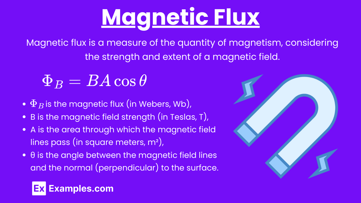
Magnetic Flux (): Magnetic flux is a measure of the quantity of magnetism, considering the strength and extent of a magnetic field. It is represented by the symbol and is calculated as the product of the magnetic field (B), the area through which the field lines pass (A), and the cosine of the angle (θ) between the magnetic field and the normal to the surface.
Formula:
where:
is the magnetic flux (in Webers, Wb),
B is the magnetic field strength (in Teslas, T),
A is the area through which the magnetic field lines pass (in square meters, m²),
θ is the angle between the magnetic field lines and the normal (perpendicular) to the surface.
Key Points:
Magnetic flux is maximized when the magnetic field is perpendicular to the surface (θ = 0).
Magnetic flux is zero when the magnetic field is parallel to the surface (θ = 90⁰).
Applications of Magnetic Flux
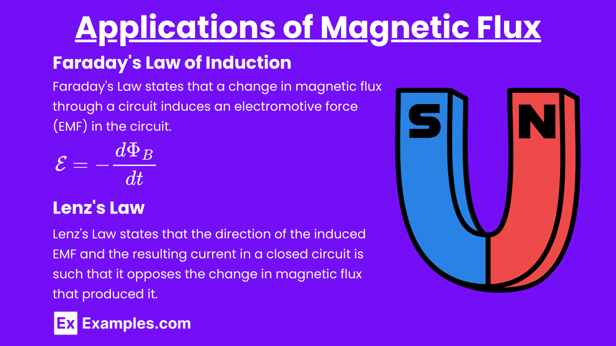
Faraday's Law of Induction
Faraday's Law of Induction: Faraday's Law states that a change in magnetic flux through a circuit induces an electromotive force (EMF) in the circuit.
Formula:
where:
E is the induced EMF (in Volts, V),
is the rate of change of magnetic flux.
Lenz's Law
Lenz's Law: Lenz's Law states that the direction of the induced EMF and the resulting current in a closed circuit is such that it opposes the change in magnetic flux that produced it.
Example 1
Calculating Magnetic Flux through a Coil
Scenario: A coil with 50 turns and an area of 0.1m² is placed in a uniform magnetic field of 0.2T. The magnetic field is perpendicular to the plane of the coil. Calculate the magnetic flux through the coil.
Solution:
Since there are 50 turns: Φₜₒₜₐₗ = 50×0.02
Φₜₒₜₐₗ = 1Wb
Example 2
Magnetic Flux through an Inclined Surface
Scenario: A rectangular loop with an area of 0.5m² is placed in a uniform magnetic field of 0.3T. The angle between the magnetic field and the normal to the loop's surface is 30⁰. Calculate the magnetic flux through the loop.
Solution:
Example 3
Induced EMF in a Changing Magnetic Field
Scenario: A circular loop with a radius of 0.1m is placed in a magnetic field that changes uniformly from 0.1T to 0.5T in 2 seconds. Calculate the induced EMF.
Solution: First, calculate the area of the loop: A = πr²
A = π(0.1)²
A = 0.0314m²
Calculate the change in magnetic flux:
Calculate the induced EMF:
Example 4
Induced Current in a Rotating Loop
Scenario: A square loop with a side length of 0.2m is rotating in a magnetic field of 0.4T. The loop completes one rotation in 0.5 seconds. Calculate the average induced EMF during one rotation.
Solution: First, calculate the area of the loop: A = (0.2)²
A = 0.04m²
Since the loop completes one rotation, the angle changes from 0⁰ to 360⁰:
(initial) =BAcos0⁰ = 0.4×0.04×1 = 0.016Wb
(final) = BAcos360⁰ = 0.4×0.04×1 = 0.016Wb
The change in flux over one rotation is:
ΔΦB = (final) − (initial)
Since the loop returns to the same orientation, ΔΦB = 0Wb.
Calculate the induced EMF:
The average induced EMF over one complete rotation is zero because the magnetic flux returns to its initial value.
Example 5
Induced EMF in a Moving Conductor
Scenario: A 0.5-meter-long conducting rod moves perpendicular to a uniform magnetic field of 0.3T with a speed of 2m/s. Calculate the induced EMF across the rod.
Solution: E = Blv
where:
E is the induced EMF,
B is the magnetic field strength,
l is the length of the conductor,
v is the speed of the conductor.
E = 0.3×0.5×2
E = 0.3×1
E = 0.3V
Practice Problems
Question 1:
Which of the following factors does NOT affect the magnetic flux through a surface?
A) The strength of the magnetic field
B) The area of the surface
C) The orientation of the surface with respect to the magnetic field
D) The material of the surface
Answer: D) The material of the surface
Explanation:
Magnetic flux () is given by the formula:
= B⋅A⋅cos(θ)
where:
B is the magnetic field strength,
A is the area of the surface,
θ is the angle between the magnetic field and the normal to the surface.
The material of the surface does not affect the magnetic flux. The magnetic flux depends only on the strength of the magnetic field, the area of the surface, and the orientation of the surface relative to the magnetic field.
Question 2:
A loop of wire with an area of 0.1 m² is placed in a uniform magnetic field of 0.5 T. If the plane of the loop is perpendicular to the magnetic field, what is the magnetic flux through the loop?
A) 0 Wb
B) 0.05 Wb
C) 0.1 Wb
D) 0.5 Wb
Answer: C) 0.1 Wb
Explanation:
The magnetic flux (ΦB) through the loop is given by:
= B⋅A⋅cos(θ)
Since the plane of the loop is perpendicular to the magnetic field, θ=0∘ and cos(0∘)=1.
Given:
B = 0.5T
A = 0.1m²
Calculate the magnetic flux:
= 0.5T×0.1m²×1 = 0.05Wb
Thus, the correct answer is 0.05 Wb.
Question 3:
If the magnetic flux through a coil changes from 0.3 Wb to 0.1 Wb in 2 seconds, what is the average induced EMF in the coil according to Faraday's Law of Induction?
A) 0.1 V
B) 0.2 V
C) 0.5 V
D) 1 V
Answer: B) 0.1 V
Explanation:
Faraday's Law of Induction states that the induced EMF (ϵ) in a coil is given by the rate of change of magnetic flux through the coil:
Given:
Initial magnetic flux (ΦB1) = 0.3 Wb
Final magnetic flux (ΦB2) = 0.1 Wb
Time interval (Δt) = 2 s
Calculate the change in magnetic flux:
Calculate the average induced EMF:
Thus, the correct answer is 0.1 V.