
Resistance and Capacitance

![\[ R = \rho \frac{L}{A} \]](https://www.examples.com/wp-content/ql-cache/quicklatex.com-f57dccb96a7bd28af797e2524c18dc05_l3.svg "Rendered by QuickLaTeX.com")
![\[ C = \frac{Q}{V} \]](https://www.examples.com/wp-content/ql-cache/quicklatex.com-17f8e9307332f62a728e632ed27042ed_l3.svg "Rendered by QuickLaTeX.com")
![\[ C = \epsilon_0 \frac{A}{d} \]](https://www.examples.com/wp-content/ql-cache/quicklatex.com-f6e644c306285d7167911b2a77b63f68_l3.svg "Rendered by QuickLaTeX.com")
![\[ R_{\text{eq}} = R_1 + R_2 + R_3 + \cdots \]](https://www.examples.com/wp-content/ql-cache/quicklatex.com-a16e385e5ef5d9352252b098abacea96_l3.svg "Rendered by QuickLaTeX.com")
![\[ \frac{1}{R_{\text{eq}}} = \frac{1}{R_1} + \frac{1}{R_2} + \frac{1}{R_3} + \cdots \]](https://www.examples.com/wp-content/ql-cache/quicklatex.com-42c9f9811df99444d7acc979418c542c_l3.svg "Rendered by QuickLaTeX.com")
![\[ \frac{1}{C_{\text{eq}}} = \frac{1}{C_1} + \frac{1}{C_2} + \frac{1}{C_3} + \cdots \]](https://www.examples.com/wp-content/ql-cache/quicklatex.com-16e204663b2f418ba6a1e70fe44cf2ec_l3.svg "Rendered by QuickLaTeX.com")
![\[ R = 1.68 \times 10^{-8} \frac{2}{1 \times 10^{-6}} \]](https://www.examples.com/wp-content/ql-cache/quicklatex.com-ab398ec7364a189f455b864ef1574e16_l3.svg "Rendered by QuickLaTeX.com")
![\[ R = 3.36 \times 10^{-2} \, \Omega \]](https://www.examples.com/wp-content/ql-cache/quicklatex.com-baa4faea9628452dc23db37ad3b8d245_l3.svg "Rendered by QuickLaTeX.com")
![\[ V = IR \]](https://www.examples.com/wp-content/ql-cache/quicklatex.com-a85f81cda843a8fb5d4a3d02ca73a0a0_l3.svg "Rendered by QuickLaTeX.com")
![\[ I = \frac{V}{R} \]](https://www.examples.com/wp-content/ql-cache/quicklatex.com-218f10ff77a95bdccd3d547e17db9143_l3.svg "Rendered by QuickLaTeX.com")
![\[ I = \frac{10 \, \text{V}}{5 \, \Omega} \]](https://www.examples.com/wp-content/ql-cache/quicklatex.com-5fd87506cae499cfc160e417026b2649_l3.svg "Rendered by QuickLaTeX.com")
![\[ I = 2 \, \text{A} \]](https://www.examples.com/wp-content/ql-cache/quicklatex.com-3caac6443e844c175d0312092459d654_l3.svg "Rendered by QuickLaTeX.com")
![\[ C = 8.854 \times 10^{-12} \frac{2}{0.01} \]](https://www.examples.com/wp-content/ql-cache/quicklatex.com-225ef7fe7d54829b1c56dfbf179dc068_l3.svg "Rendered by QuickLaTeX.com")
![\[ C = 1.77 \times 10^{-9} \, \text{F} \]](https://www.examples.com/wp-content/ql-cache/quicklatex.com-85ca0a4bd41a1ac51eba29e38ede4589_l3.svg "Rendered by QuickLaTeX.com")
![\[ C = 1.77 \, \text{nF} \]](https://www.examples.com/wp-content/ql-cache/quicklatex.com-7580c72511e2ee503c1f2fcb7cc57106_l3.svg "Rendered by QuickLaTeX.com")
![\[ R_{eq} = R_1 + R_2 + R_3 \]](https://www.examples.com/wp-content/ql-cache/quicklatex.com-cac74f08854557726548ff7c90a26849_l3.svg "Rendered by QuickLaTeX.com")
![\[ R_{eq} = 2 + 3 + 5 \]](https://www.examples.com/wp-content/ql-cache/quicklatex.com-a12a88e0f0e36faf746b3ff2799e09c1_l3.svg "Rendered by QuickLaTeX.com")
![\[ R_{eq} = 10 \, \Omega \]](https://www.examples.com/wp-content/ql-cache/quicklatex.com-0202ff7cda9c337973d762624eb1c730_l3.svg "Rendered by QuickLaTeX.com")
![\[ C_{eq} = C_1 + C_2 + C_3 \]](https://www.examples.com/wp-content/ql-cache/quicklatex.com-a34fff4f3da8b781f09cf2f4155a5e32_l3.svg "Rendered by QuickLaTeX.com")
![\[ C_{eq} = 2 + 3 + 5 \]](https://www.examples.com/wp-content/ql-cache/quicklatex.com-a97bc0ba0a9d8a31941775d1b6890956_l3.svg "Rendered by QuickLaTeX.com")
![\[ C_{eq} = 10 \, \mu F \]](https://www.examples.com/wp-content/ql-cache/quicklatex.com-27f0fed71d7c45b47f2e3511379cb54e_l3.svg "Rendered by QuickLaTeX.com")
![\[ R' = \rho \frac{2L}{\frac{A}{2}} = \rho \frac{2L}{0.5A} = \rho \frac{4L}{A} \]](https://www.examples.com/wp-content/ql-cache/quicklatex.com-5ebdda1fe033b180e519199b9ab8fb9e_l3.svg "Rendered by QuickLaTeX.com")
![\[ C = \epsilon \frac{A}{d} \]](https://www.examples.com/wp-content/ql-cache/quicklatex.com-786a43a0468723de39d5c75c8012d414_l3.svg "Rendered by QuickLaTeX.com")
![\[ V(t) = V_{\text{source}} \left(1 - e^{\frac{-t}{RC}}\right) \]](https://www.examples.com/wp-content/ql-cache/quicklatex.com-bb3c6087a175085c82d30919e7484c10_l3.svg "Rendered by QuickLaTeX.com")
![\[e^{\frac{-t}{RC}}\]](https://www.examples.com/wp-content/ql-cache/quicklatex.com-4b02fbfa74ae809d5e7527c4ec62c71a_l3.svg "Rendered by QuickLaTeX.com")
Understanding resistance and capacitance is crucial for mastering the principles of electricity and circuits in the AP Physics exam. These topics cover the behavior of resistors and capacitors, and their roles in electrical circuits. Below are detailed notes along with five examples to help you achieve a high score on your AP Physics exam.
Free AP Physics 2: Algebra-Based Practice Test
Learning Objectives
In studying resistance and capacitance for the AP Physics exam, you should understand the principles of Ohm's Law, the relationship between voltage, current, and resistance in series and parallel circuits, and how to calculate equivalent resistance. Additionally, you should grasp the concept of capacitance, the function of capacitors in circuits, and the formulas for calculating capacitance in series and parallel configurations. Analyzing RC circuits and understanding time constants will also be crucial.
Resistance
Resistance (R): Resistance is a measure of the opposition to the flow of electric current in a conductor. It is defined by Ohm's Law.
Ohm’s Law: V = IR
where:
V is the voltage (in volts, V),
I is the current (in amperes, A),
R is the resistance (in ohms, Ω).
Key Points:
Resistance depends on the material, length, and cross-sectional area of the conductor.
Conductors have low resistance, while insulators have high resistance.
Factors Affecting Resistance
Material: Different materials have different intrinsic resistivities (ρ).
Length (L): Resistance is directly proportional to the length of the conductor.
Cross-sectional Area (A): Resistance is inversely proportional to the cross-sectional area.
Formula: R = \rho \frac{L}{A}
where:
ρ is the resistivity of the material (in ohm-meters, Ω·m).
Capacitance
Capacitance (C): Capacitance is the ability of a system to store electric charge per unit voltage.
Formula: C = \frac{Q}{V}
where:
C is the capacitance (in farads, F),
Q is the charge (in coulombs, C),
V is the voltage (in volts, V).
Parallel Plate Capacitor
Capacitance of a Parallel Plate Capacitor:
where: C = \epsilon_0 \frac{A}{d}
ϵ₀ is the permittivity of free space (8.854×10⁻¹² F/m),
A is the area of one plate (in square meters, m²),
d is the separation between the plates (in meters, m).
Series and Parallel Configurations
Resistors in Series
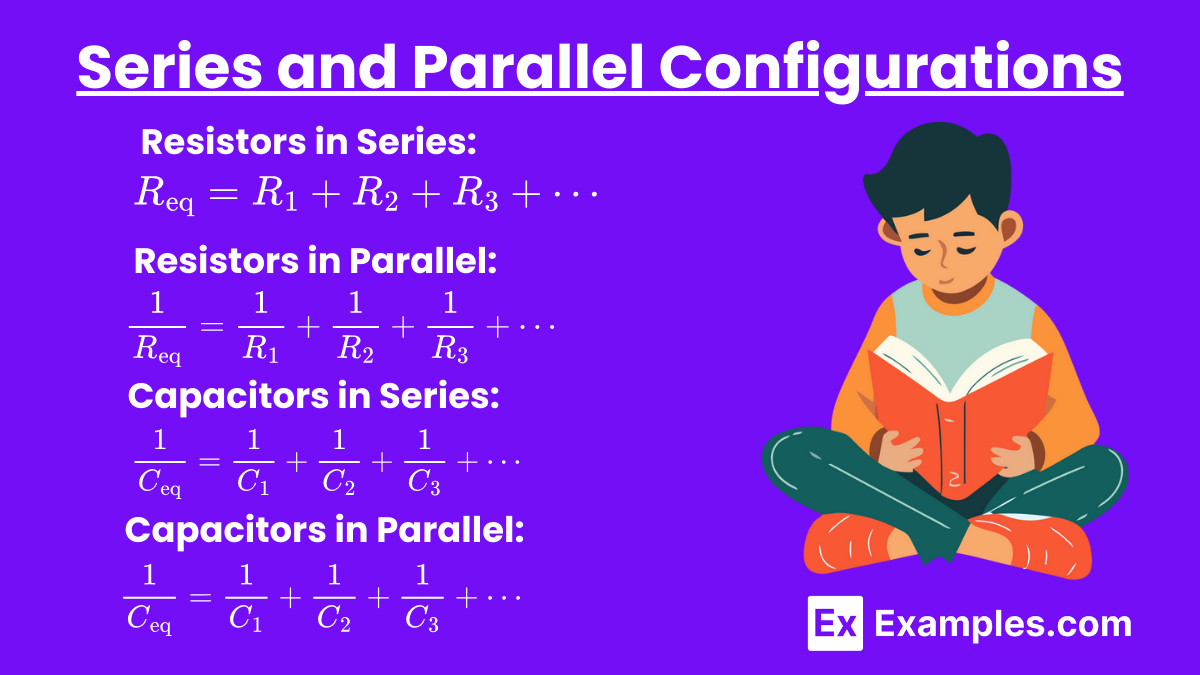
Equivalent Resistance: R_{\text{eq}} = R_1 + R_2 + R_3 + \cdots
Resistors in Parallel
Equivalent Resistance: \frac{1}{R_{\text{eq}}} = \frac{1}{R_1} + \frac{1}{R_2} + \frac{1}{R_3} + \cdots
Capacitors in Series
Equivalent Capacitance: \frac{1}{C_{\text{eq}}} = \frac{1}{C_1} + \frac{1}{C_2} + \frac{1}{C_3} + \cdots
Capacitors in Parallel
Equivalent Capacitance: \frac{1}{C_{\text{eq}}} = \frac{1}{C_1} + \frac{1}{C_2} + \frac{1}{C_3} + \cdots
Example 1
Calculating Resistance
Scenario: A copper wire (resistivity ρ = 1.68×10⁻⁸Ω⋅m) has a length of 2 meters and a cross-sectional area of 1×10⁻⁶m². Calculate its resistance.
Solution: R = \rho \frac{L}{A} R = 1.68 \times 10^{-8} \frac{2}{1 \times 10^{-6}} R = 3.36 \times 10^{-2} \, \Omega
Example 2
Ohm’s Law Application
Scenario: A resistor with a resistance of 5Ω is connected to a 10 V battery. Calculate the current flowing through the resistor.
Solution: V = IR I = \frac{V}{R} I = \frac{10 \, \text{V}}{5 \, \Omega} I = 2 \, \text{A}
Example 3
Capacitance of a Parallel Plate Capacitor
Scenario: A parallel plate capacitor has an area of 2m² and a separation of 0.01m. Calculate the capacitance.
Solution: C = \epsilon_0 \frac{A}{d} C = 8.854 \times 10^{-12} \frac{2}{0.01} C = 1.77 \times 10^{-9} \, \text{F} C = 1.77 \, \text{nF}
Example 4
Equivalent Resistance in Series
Scenario: Three resistors of 2Ω, 3Ω, and 5Ω are connected in series. Calculate the equivalent resistance.
Solution: R_{eq} = R_1 + R_2 + R_3 R_{eq} = 2 + 3 + 5 R_{eq} = 10 \, \Omega
Example 5
Equivalent Capacitance in Parallel
Scenario: Three capacitors of 2μF, 3μF, and 5μF are connected in parallel. Calculate the equivalent capacitance.
Solution: C_{eq} = C_1 + C_2 + C_3 C_{eq} = 2 + 3 + 5 C_{eq} = 10 \, \mu F
Practice Problems
Question 1
What happens to the resistance of a wire if its length is doubled and its cross-sectional area is halved?
A) The resistance remains the same.
B) The resistance doubles.
C) The resistance quadruples.
D) The resistance halves.
Answer: C) The resistance quadruples.
Explanation:
The resistance R of a wire is given by:
R = ρAL
where ρ is the resistivity of the material, L is the length of the wire, and A is the cross-sectional area. If the length L is doubled and the cross-sectional area A is halved, the new resistance R′ is:
R' = \rho \frac{2L}{\frac{A}{2}} = \rho \frac{2L}{0.5A} = \rho \frac{4L}{A}
Thus, the resistance quadruples.
Question 2
Which of the following changes would increase the capacitance of a parallel plate capacitor?
A) Increasing the distance between the plates.
B) Decreasing the area of the plates.
C) Inserting a dielectric material between the plates.
D) Removing the dielectric material between the plates.
Answer: C) Inserting a dielectric material between the plates.
Explanation:
The capacitance C of a parallel plate capacitor is given by:
C = \epsilon \frac{A}{d}
where ϵ is the permittivity of the dielectric material between the plates, A is the area of the plates, and d is the distance between the plates. Inserting a dielectric material increases the permittivity ϵ, thereby increasing the capacitance.
Question 3
A capacitor is initially uncharged. It is then connected to a DC voltage source. Which of the following statements is true about the charging process?
A) The voltage across the capacitor rises linearly with time.
B) The current through the capacitor is constant throughout the charging process.
C) The voltage across the capacitor eventually equals the source voltage.
D) The capacitor discharges immediately after being connected to the source.
Answer: C) The voltage across the capacitor eventually equals the source voltage.
Explanation:
When a capacitor is connected to a DC voltage source, it starts to charge. The voltage across the capacitor V as a function of time t is given by:
V(t) = V_{\text{source}} \left(1 - e^{\frac{-t}{RC}}\right)
where Vₛₒᵤᵣ꜀ₑ is the source voltage, R is the resistance in the circuit, and C is the capacitance. As time t approaches infinity,
e^{\frac{-t}{RC}}
approaches zero, and the voltage across the capacitor V(t) approaches Vₛₒᵤᵣ꜀ₑ. Therefore, the voltage across the capacitor eventually equals the source voltage.