Capacitors


A capacitor is a crucial component in electronics, used to store and release electrical energy. It consists of two conductive plates separated by an insulating material called a dielectric. In AP Physics, understanding capacitors involves studying their ability to store charge, their behavior in circuits, and their various applications. Capacitors play vital roles in filtering, energy storage, and signal processing. Mastery of capacitors, including their mathematical relationships and practical uses, is essential for success in AP Physics exams.
Free AP Physics C: Electricity and Magnetism Practice Test
Learning Objectives
When studying capacitors for the AP Physics exam, you should understand the principles of capacitance, including how capacitors store and release energy. Learn to calculate capacitance, charge, and energy stored using relevant formulas. Understand series and parallel capacitor combinations, their equivalent capacitances, and the concept of the time constant in RC circuits. Familiarize yourself with capacitor charging and discharging behaviors, practical applications, and solve related problems. These objectives will help you grasp the fundamental concepts and apply them effectively in exam scenarios.
Capacitors
A capacitor is an electrical component that stores electrical energy in an electric field. It is a passive electronic component with two terminals. A capacitor consists of two conductive plates separated by an insulating material known as the dielectric. When a voltage is applied across the terminals, an electric field develops across the dielectric, causing positive charge to collect on one plate and negative charge on the other.
Capacitance
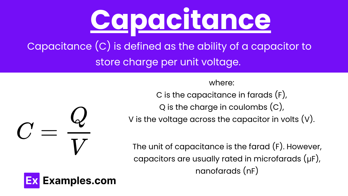
Capacitance (C) is defined as the ability of a capacitor to store charge per unit voltage. It is given by the formula:
where:
C is the capacitance in farads (F),
Q is the charge in coulombs (C),
V is the voltage across the capacitor in volts (V).
Unit of Capacitance
The unit of capacitance is the Farad (F). However, capacitors are usually rated in microfarads (μF), nanofarads (nF), or picofarads (pF) because 1 farad is quite large.
Types of Capacitors
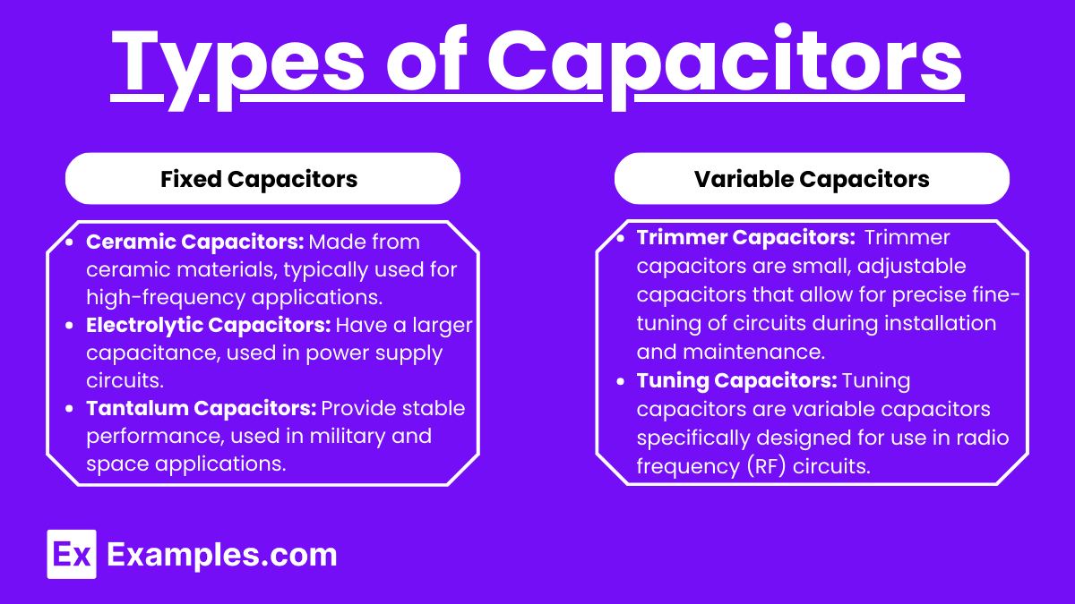
Fixed Capacitors
Ceramic Capacitors: Made from ceramic materials, typically used for high-frequency applications.
Electrolytic Capacitors: Have a larger capacitance, used in power supply circuits.
Tantalum Capacitors: Provide stable performance, used in military and space applications.
Variable Capacitors
Trimmer Capacitors: Used for fine-tuning circuits. Trimmer capacitors are small, adjustable capacitors that allow for precise fine-tuning of circuits during installation and maintenance.
Tuning Capacitors: Tuning capacitors are variable capacitors specifically designed for use in radio frequency (RF) circuits.
Capacitors in Circuits
Series and Parallel Combinations
Series Combination
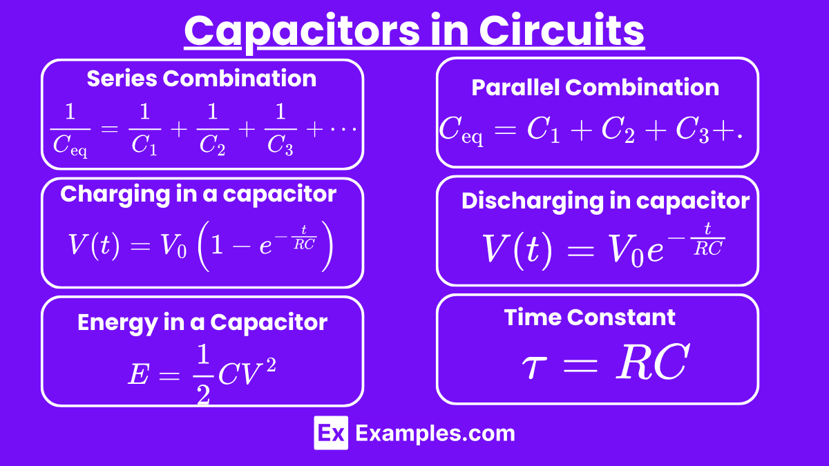
For capacitors in series, the total or equivalent capacitance Ceq is given by:
Parallel Combination
For capacitors in parallel, the total or equivalent capacitance Ceq is given by:
Energy Stored in a Capacitor
The energy E stored in a capacitor is given by:
where:
E is the energy in joules (J),
C is the capacitance in farads (F),
V is the voltage across the capacitor in volts (V).
Charging and Discharging
Charging
When a capacitor is connected to a DC voltage source through a resistor, it charges up over time. The voltage across the capacitor V(t) as a function of time ttt is given by:
where:
V0 is the supply voltage,
R is the resistance,
C is the capacitance,
t is the time,
e is the base of the natural logarithm.
Discharging
When a charged capacitor is connected across a resistor, it discharges over time. The voltage across the capacitor V(t) as a function of time ttt is given by:
Time Constant
The time constant τ\tauτ of an RC circuit (a circuit with a resistor and a capacitor) is given by:
It represents the time required for the voltage across the capacitor to reach approximately 63% of its final value during charging or to decay to approximately 37% of its initial value during discharging.
Applications of Capacitors
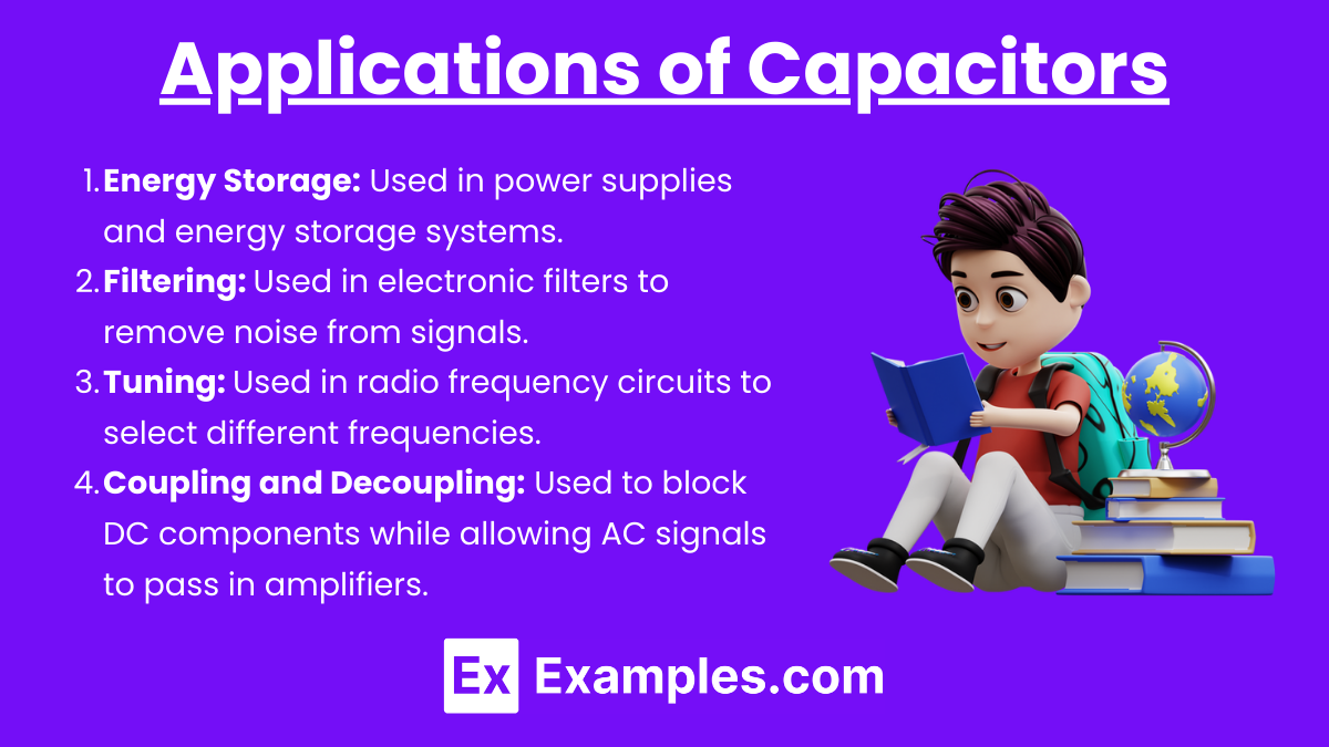
Energy Storage: Used in power supplies and energy storage systems.
Filtering: Used in electronic filters to remove noise from signals.
Tuning: Used in radio frequency circuits to select different frequencies.
Coupling and Decoupling: Used to block DC components while allowing AC signals to pass in amplifiers.
Examples
Example 1: Ceramic Capacitors
Description: Small, non-polarized capacitors often used in high-frequency applications.
Usage: Found in RF circuits, decoupling, and bypass applications.
Example 2 : Electrolytic Capacitors
Description: Polarized capacitors with high capacitance values, usually used where large capacitance is required.
Usage: Commonly used in power supply circuits and audio amplifiers.
Example 3 : Tantalum Capacitors
Description: Polarized capacitors known for their stability and reliability.
Usage: Used in military applications, medical devices, and portable electronic devices.
Example 4 : Film Capacitors
Description: Non-polarized capacitors made with thin plastic film as the dielectric.
Usage: Used in applications requiring low noise, such as audio equipment and precision timing circuits.
Example 5: Supercapacitors
Description: Also known as ultracapacitors, these capacitors have very high capacitance values.
Usage: Used in energy storage applications, regenerative braking systems in vehicles, and memory backup systems.
Multiple Choice Questions
Question 1
Which of the following correctly describes the function of a capacitor in an electric circuit?
A) A capacitor stores electrical energy in the form of magnetic fields.
B) A capacitor stores electrical energy in the form of an electric field.
C) A capacitor converts electrical energy into mechanical energy.
D) A capacitor converts electrical energy into thermal energy.
Answer: B) A capacitor stores electrical energy in the form of an electric field.
Explanation: Capacitors store electrical energy by maintaining a separation of electric charge. When a voltage is applied across the terminals of a capacitor, an electric field develops across the insulating material (dielectric) between the capacitor's plates. This field stores energy in the form of potential energy due to the separation of positive and negative charges on the opposite plates. This energy can be released when the capacitor discharges, making capacitors useful for various applications such as smoothing out voltage fluctuations in power supplies, timing applications, and energy storage in electronic circuits.
Question 2
Which parameter of a capacitor is defined as the ratio of the electric charge (Q) on each conductor to the potential difference (V) between them?
A) Resistance
B) Inductance
C) Capacitance
D) Conductance
Answer: C) Capacitance
Explanation: Capacitance (C) is a measure of a capacitor's ability to store charge per unit voltage. It is defined by the formula , where Q is the charge stored on one plate of the capacitor and V is the potential difference between the plates. The unit of capacitance is the farad (F). A higher capacitance indicates a greater ability to store charge at a given voltage. Capacitance depends on the physical characteristics of the capacitor, such as the area of the plates, the distance between them, and the properties of the dielectric material between the plates.
Question 3
In an RC (Resistor-Capacitor) circuit, what happens to the voltage across the capacitor over time when a constant voltage is first applied to the circuit?
A) The voltage across the capacitor immediately reaches the applied voltage.
B) The voltage across the capacitor decreases exponentially.
C) The voltage across the capacitor increases linearly with time.
D) The voltage across the capacitor increases exponentially until it equals the applied voltage.
Answer: D) The voltage across the capacitor increases exponentially until it equals the applied voltage.
Explanation: In an RC circuit, when a constant voltage is applied, the voltage across the capacitor does not immediately reach the applied voltage. Instead, it increases exponentially according to the formula , where V0 is the applied voltage, R is the resistance, C is the capacitance, and t is time. This behavior is due to the time it takes for the capacitor to accumulate charge. The product RC, known as the time constant (τ), determines how quickly the capacitor charges. After a period of about 5τ, the voltage across the capacitor is very close to the applied voltage, effectively reaching steady state.