
Current Resistance and Power

Current, resistance, and power are fundamental concepts in electricity that are essential for understanding how electrical circuits operate. In AP Physics, these topics are interconnected, with current representing the flow of electric charge, resistance quantifying the opposition to this flow, and power describing the rate at which electrical energy is consumed or converted. Mastery of these concepts is crucial for analyzing circuits, solving complex problems, and achieving a strong performance on the AP Physics exam.
Learning Objectives
By studying current, resistance, and power, you should understand how electric current flows through circuits, the factors affecting resistance in materials, and how to calculate the power dissipated in electrical components. You should be able to apply Ohm’s Law to solve circuit problems, analyze series and parallel circuits, and use different power formulas to determine energy consumption. Mastering these concepts will prepare you for questions involving circuit analysis and energy efficiency on the AP Physics exam.
1. Electric Current (I)
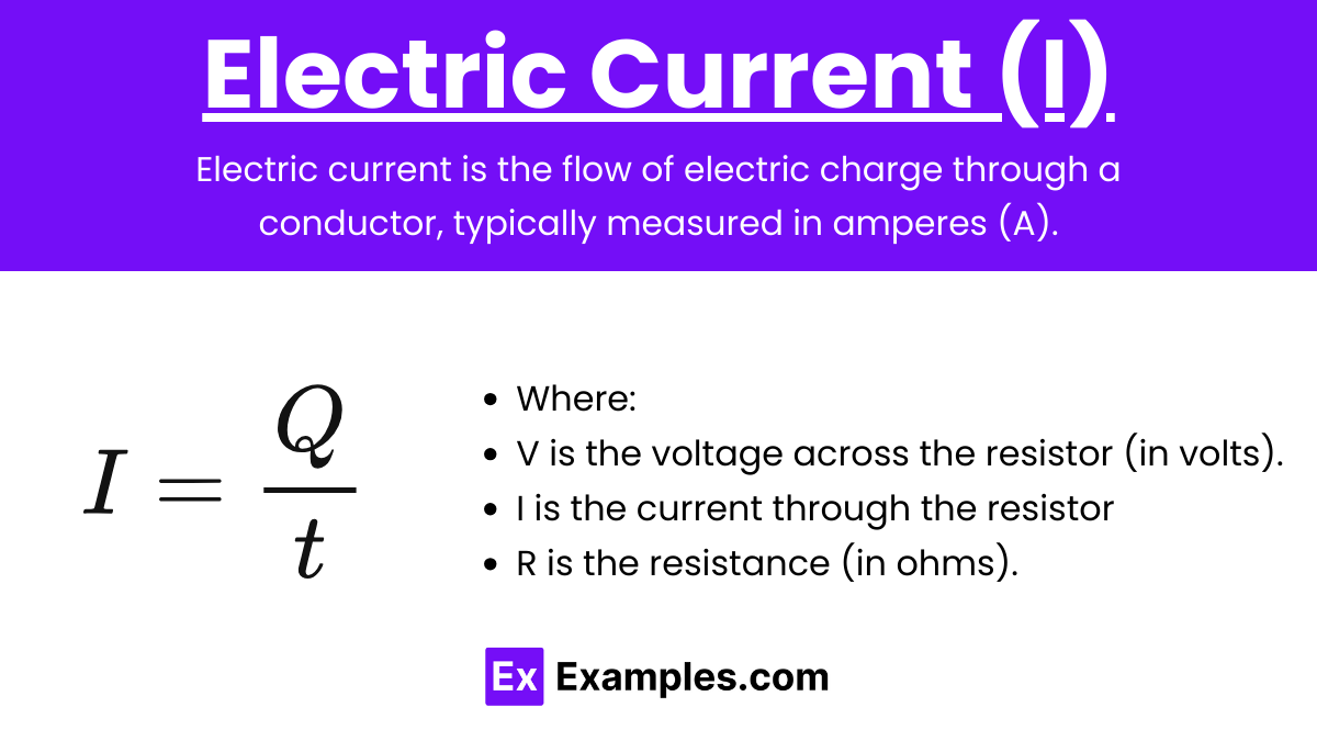
Electric current is the flow of electric charge through a conductor, typically measured in amperes (A). The current is essentially the rate at which charge flows through a point in the circuit.
Formula: 
where:
- I = current (amperes, A)
- Q = charge (coulombs, C)
- t = time (seconds, s)
Direction of Current:
- Conventional Current: Flows from the positive terminal to the negative terminal of a battery or power supply. This direction is based on the assumption that current is carried by positive charges.
- Electron Flow: The actual flow of electrons, which is from the negative terminal to the positive terminal, opposite to conventional current.
2. Resistance (R)
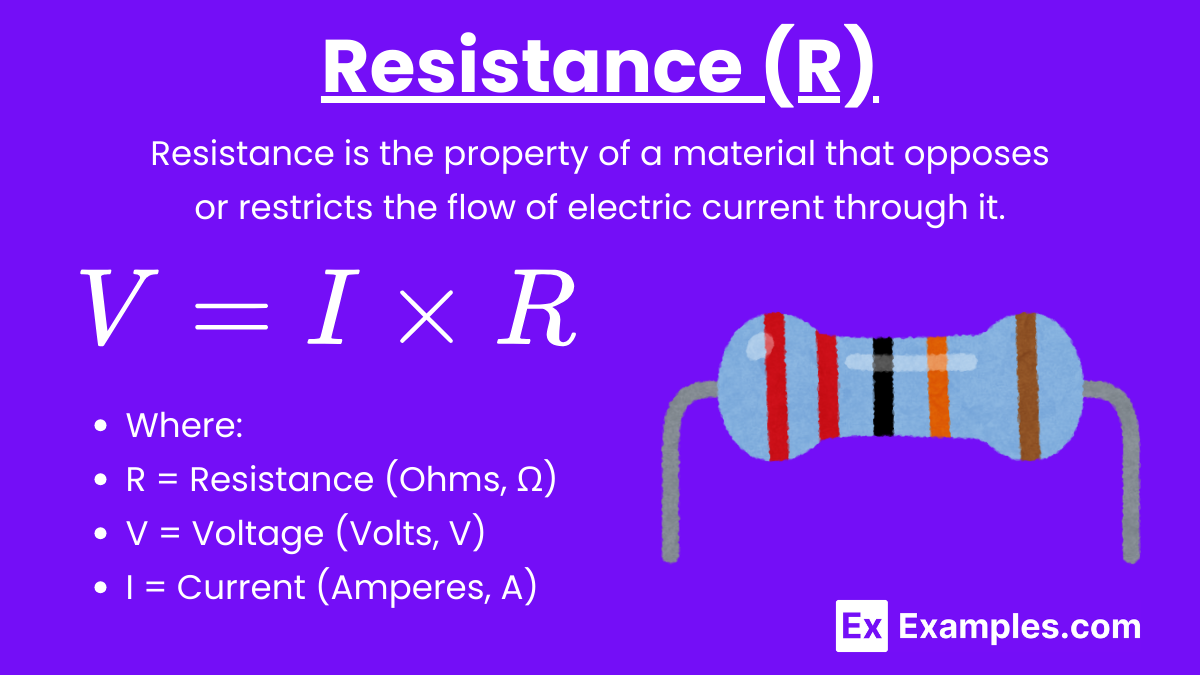
Resistance is a measure of the opposition to the flow of current in a conductor. It’s measured in ohms (Ω).
Ohm’s Law: V=IR
where:
- V = voltage (volts, V)
- I = current (amperes, A)
- R = resistance (ohms, Ω)
Factors Affecting Resistance:
- Material: Conductors (like copper) have low resistance, while insulators (like rubber) have high resistance.
- Length of the Conductor (L): Resistance is directly proportional to the length. Longer wires have more resistance.
- Cross-sectional Area (A): Resistance is inversely proportional to the cross-sectional area. Thicker wires have less resistance.
- Temperature: For most materials, resistance increases with temperature.
Resistors in Circuits:
- Series Circuit:
- Total resistance RtotalR_{\text{total}}Rtotal is the sum of individual resistances:

- The same current flows through each resistor.
- Total resistance RtotalR_{\text{total}}Rtotal is the sum of individual resistances:
- Parallel Circuit:
- The reciprocal of the total resistance RtotalR_{\text{total}}Rtotal is the sum of the reciprocals of the individual resistances:

- The voltage across each resistor is the same.
- The reciprocal of the total resistance RtotalR_{\text{total}}Rtotal is the sum of the reciprocals of the individual resistances:
3. Electric Power
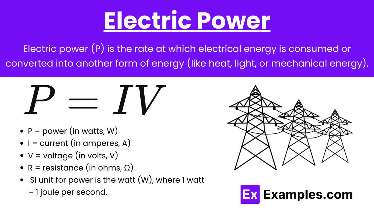
Electric power (P) is the rate at which electrical energy is consumed or converted into another form of energy (like heat, light, or mechanical energy).
Unit:
The SI unit for power is the watt (W), where 1 watt = 1 joule per second.
Power Formulas:
Power can be calculated using the following formulas, derived from Ohm’s Law:


- P = power (in watts, W)
- I = current (in amperes, A)
- V = voltage (in volts, V)
- R = resistance (in ohms, Ω)
Applications and Practical Considerations
- Electrical Devices: The power rating on devices indicates how much energy they consume or output, which can be calculated using the above formulas.
- Efficiency: Power efficiency is important in circuits, particularly in minimizing energy loss as heat.
- Voltage Drop Across a Resistor:
- The voltage drop across a resistor in a circuit can be calculated using Ohm’s Law, V=IR.
- Power Ratings of Devices:
- Electrical devices have a power rating indicating the maximum power they can safely use or dissipate. Exceeding this rating can cause overheating or damage.
- Electrical Safety:
- Fuses and Circuit Breakers: Protect circuits from excessive current. A fuse melts, and a circuit breaker trips when the current exceeds a safe level, breaking the circuit.
- Insulation: Prevents unintended current flow and protects users from electric shock.
- Power Efficiency:
- Power Loss in Transmission Lines: Power loss due to resistance in wires is proportional to
 . High-voltage, low-current transmission minimizes losses over long distances.
Examples
Here are five examples illustrating the concepts of current, resistance, and power:
Example 1: Household Light Bulb
In a typical household light bulb, electricity flows through a tungsten filament. The filament has a certain resistance, which causes it to heat up and emit light when current passes through it. For instance, a 60-watt bulb operating on a 120-volt circuit draws 0.5 amps of current. The resistance of the filament can be calculated using Ohm’s law, R=V/IR = V/IR=V/I, resulting in a resistance of 240 ohms. The power consumed by the bulb is given by the formula P=VIP = VIP=VI, which in this case is 60 watts.
Example 2: Electric Heater
An electric heater converts electrical energy into heat energy by passing current through a high-resistance wire, typically made of nichrome. If the heater operates at 1500 watts on a 120-volt circuit, it draws 12.5 amps of current. The resistance of the heating element is 9.6 ohms. The heater’s power consumption, which is the product of the voltage and current, illustrates the relationship between power and resistance in resistive heating.
Example 3: Smartphone Charger
A smartphone charger converts high voltage AC from the wall outlet to low voltage DC suitable for the phone. If a charger supplies 2 amps of current at 5 volts to the phone, it is delivering 10 watts of power. The resistance of the circuit can be calculated if the voltage drop across the charger is known. For instance, if the internal resistance of the charger circuit is 0.5 ohms, using Ohm’s law, the voltage drop can be calculated, and the power dissipation in the charger itself can be determined.
Example 4: Electric Fan
An electric fan uses a motor to convert electrical energy into mechanical energy, causing the fan blades to rotate. If the fan motor operates at 100 watts on a 220-volt circuit, it draws approximately 0.45 amps of current. The resistance of the motor windings is about 490 ohms. The power consumed by the fan is a combination of the electrical power converted into mechanical work and the power lost as heat due to the resistance of the windings.
Example 5: Electric Car
In an electric vehicle, the motor converts electrical energy from the battery into mechanical energy to drive the car. If the motor operates at 400 volts and draws 100 amps of current, it uses 40,000 watts or 40 kilowatts of power. The resistance in the motor windings and the internal resistance of the battery both contribute to power loss in the form of heat. The efficiency of the motor and the power management system in the car determine how much of this power is effectively used to drive the vehicle.
Multiple Choice Questions
Question 1
Which of the following correctly describes the relationship between current, voltage, and resistance according to Ohm’s Law?
a) I=VR
b) V=I×RV
c) R=VI
d) All of the above
Answer: d) All of the above
Explanation: Ohm’s Law is fundamental in understanding the relationship between current (I), voltage (V), and resistance (R). The law is usually written as:
- V=I×R (Voltage = Current × Resistance)
From this equation, we can also derive:
- I=VR (Current = Voltage ÷ Resistance)
- R=V/I (Resistance = Voltage ÷ Current)
All these expressions are correct and describe different ways to interpret Ohm’s Law, depending on which quantity you are solving for. Therefore, all of the given options are correct.
Question 2
If a resistor of 10 ohms is connected to a 12V battery, what is the power dissipated by the resistor?
a) 1.2 W
b) 12 W
c) 14.4 W
d) 24 W
Answer: c) 14.4 W
Explanation: To find the power dissipated by the resistor, we can use the power formula:
Given:
- Voltage, V=12
- Resistance, R=10
Substituting the values:
P=(12 V)2/10 ohms=144 V2/10 ohms=14.4 W
So, the power dissipated by the resistor is 14.4 W.
Alternatively, you can also use P=I×V after finding the current using Ohm’s Law.
First, calculate the current:
I=V/R=12 V/10 ohms = 1.2A
Then, calculate power:
P=I×V=1.2 A×12 V=14.4 W
Question 3
Which of the following statements is true about the relationship between power, current, and resistance?
a) Power increases with the square of the current through a resistor.
b) Power decreases with the square of the current through a resistor.
c) Power is directly proportional to the resistance.
d) Power is inversely proportional to the square of the resistance.
Answer: a) Power increases with the square of the current through a resistor.
Explanation: The power dissipated by a resistor can be expressed as:

This equation shows that power (P) is directly proportional to the square of the current (I) flowing through the resistor. This means if you double the current, the power will increase by a factor of four (since 22=4).
- Option (a) is correct because power increases with the square of the current.
- Option (b) is incorrect because it states that power decreases, which is the opposite.
- Option (c) is misleading because, while power does depend on resistance, it’s the square of the current that has a more pronounced effect.
- Option (d) is incorrect because power is directly proportional to resistance, not inversely proportional to the square of resistance.