)
Electromagnetic Induction (including Faraday’s Law and Lenz’s Law)


Electromagnetic induction is a cornerstone concept in physics that describes how a changing magnetic field induces an electric current in a conductor. In AP Physics, this topic encompasses Faraday’s Law, which quantifies the induced electromotive force (EMF), and Lenz’s Law, which determines the direction of the induced current. Understanding these laws is crucial for mastering applications such as generators and transformers, and is essential for solving related problems on the AP Physics exam.
Free AP Physics C: Electricity and Magnetism Practice Test
Learning Objectives
Understanding how a changing magnetic flux induces an electromotive force (EMF). Learn Lenz's Law to determine the direction of induced currents, ensuring they oppose changes in magnetic flux. Explore practical applications like generators and transformers. Practice solving problems involving varying magnetic fields and induced currents. Ensure you can apply these principles in real-world scenarios and solve related quantitative problems accurately.
Electromagnetic Induction
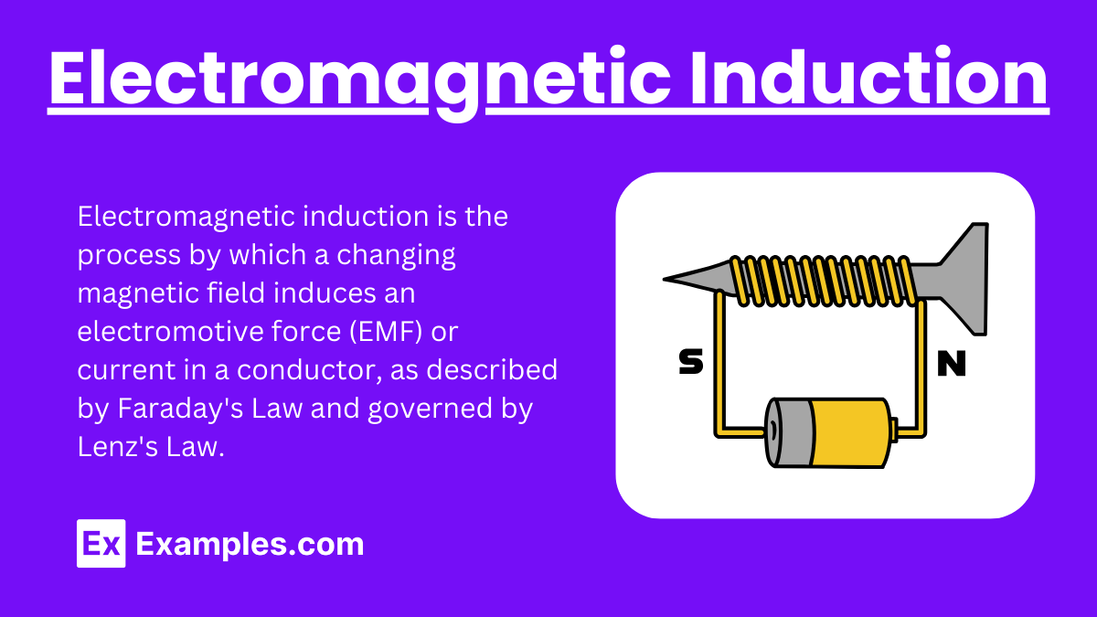
Electromagnetic induction is a fundamental concept in physics that describes how a changing magnetic field can induce an electric current in a conductor. This principle is the basis for many electrical technologies, including transformers, electric generators, and induction motors.
Faraday’s Law of Electromagnetic Induction
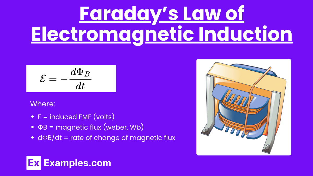
Faraday's Law states that the electromotive force (EMF) induced in a circuit is directly proportional to the rate of change of magnetic flux through the circuit.
Formula
Where:
Explanation
Magnetic Flux (ΦB): The total magnetic field passing through a given area. It is calculated as: ΦB=B⋅A⋅cos(θ)
Where:
B = magnetic field (tesla, T)
A = area (square meters, m²)
θ = angle between the magnetic field and the normal to the surface
Induced EMF: When the magnetic flux through a circuit changes, an EMF is induced. This can be due to the motion of the circuit through a magnetic field, the change in the magnetic field itself, or the deformation of the circuit.
Key Points
A positive rate of change in magnetic flux induces a negative EMF (opposite direction) due to the negative sign in Faraday's Law.
The faster the change in magnetic flux, the greater the induced EMF.
Lenz’s Law
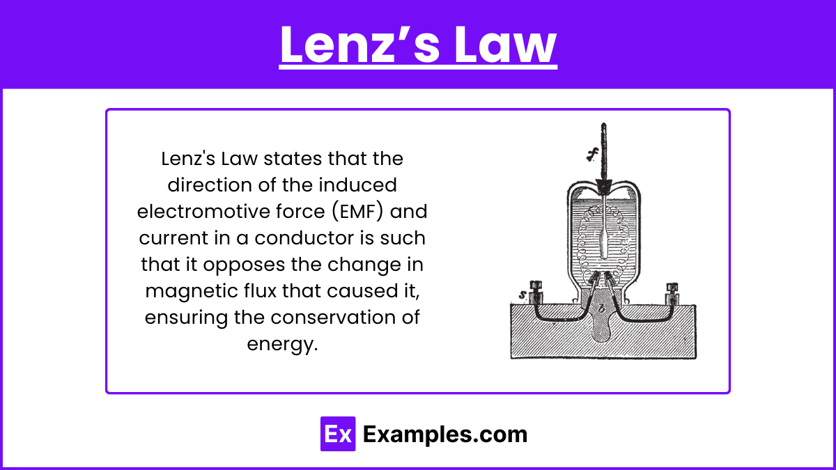
Lenz's Law states that the direction of the induced EMF and the resulting current in a closed loop is such that it opposes the change in magnetic flux that produced it.
Explanation
Lenz's Law is a consequence of the conservation of energy. It ensures that the induced current will create a magnetic field that opposes the initial change in magnetic flux.
Application
When a magnet is moved towards a coil, the induced current in the coil creates a magnetic field that opposes the magnet's motion.
When the magnet is moved away, the induced current creates a magnetic field that attempts to keep the magnet close.
Combining Faraday’s Law and Lenz’s Law
Example
Consider a loop of wire in a changing magnetic field:
Increasing Magnetic Field: If the magnetic field through the loop increases, Faraday's Law predicts an induced EMF. According to Lenz's Law, the induced current will flow in a direction that creates a magnetic field opposing the increase.
Decreasing Magnetic Field: If the magnetic field decreases, the induced EMF will generate a current that creates a magnetic field opposing the decrease.
Mathematical Representation
Combining both laws:
The negative sign ensures that the direction of the induced EMF (and thus the current) opposes the change in magnetic flux.
Practical Applications
Electric Generators
Generators convert mechanical energy into electrical energy using electromagnetic induction. When a coil rotates in a magnetic field, the changing magnetic flux induces an EMF, producing an electric current.
Transformers
Transformers use electromagnetic induction to transfer electrical energy between circuits. A changing current in the primary coil creates a changing magnetic flux, which induces an EMF in the secondary coil.
Induction Cooktops
Induction cooktops heat pots and pans using electromagnetic induction. An alternating current in a coil beneath the cooktop creates a changing magnetic field, inducing currents in the metal cookware, which heats up due to electrical resistance.
Electromagnetic Induction Summary
Faraday's Law quantifies the induced EMF from a changing magnetic flux.
Lenz's Law dictates the direction of the induced EMF, ensuring it opposes the change in magnetic flux.
These principles underpin numerous technologies, from power generation to household appliances.
Examples of Electromagnetic Induction
Electric Generators: Convert mechanical energy to electrical energy using rotating coils in a magnetic field.
Transformers: Transfer electrical energy between circuits through changing magnetic fields.
Induction Cooktops: Heat cookware by inducing currents through a changing magnetic field.
Wireless Charging: Charges devices by inducing current through a coil in a magnetic field.
Magnetic Levitation Trains: Use changing magnetic fields to induce currents that levitate and propel the train.
Practice Test Questions on Electromagnetic Induction
Question 1
What is the direction of the induced current when a magnetic field through a coil is increasing?
A. In the direction of the magnetic field
B. Opposing the increase of the magnetic field
C. In a random direction
D. There is no induced current
Answer: B. Opposing the increase of the magnetic field
Explanation: According to Lenz's Law, the direction of the induced current is such that it opposes the change in magnetic flux. If the magnetic field through a coil is increasing, the induced current will flow in a direction that creates a magnetic field opposing this increase.
Question 2
Which of the following factors does NOT affect the magnitude of the induced EMF in a coil?
A. The rate of change of the magnetic flux
B. The number of turns in the coil
C. The resistance of the coil
D. The area of the coil
Answer: C. The resistance of the coil
Explanation: The magnitude of the induced EMF depends on the rate of change of the magnetic flux, the number of turns in the coil, and the area of the coil (as these factors determine the magnetic flux). The resistance of the coil affects the current but not the EMF.
Question 3
Which of the following scenarios will NOT induce an EMF in a loop of wire?
A. Rotating the loop in a steady magnetic field
B. Moving the loop parallel to a steady magnetic field
C. Increasing the strength of the magnetic field through the loop
D. Changing the area of the loop within a magnetic field
Answer: B. Moving the loop parallel to a steady magnetic field
Explanation: Moving the loop parallel to a steady magnetic field does not change the magnetic flux through the loop, and thus no EMF is induced. In contrast, rotating the loop, increasing the magnetic field strength, and changing the loop's area all result in a change in magnetic flux, inducing an EMF.