
Fields of Long Current Carrying Wires


The study of magnetic fields generated by long current-carrying wires is a fundamental concept in electromagnetism, crucial for success in AP Physics. When an electric current flows through a wire, it creates a magnetic field around it, with properties that depend on the current's magnitude and the distance from the wire. Understanding these fields, including the forces between parallel wires and the behavior inside solenoids, is essential for mastering the electromagnetism section of the AP Physics curriculum.
Free AP Physics C: Electricity and Magnetism Practice Test
Learning Objectives
For the AP Physics exam, you should focus on understanding the principles of magnetic fields generated by long current-carrying wires. This includes mastering the Right-Hand Rule for determining the direction of the magnetic field, applying Ampère’s Law to calculate field strength, and analyzing the forces between parallel currents. Additionally, you should learn to calculate the magnetic field inside solenoids and grasp the effects of varying current and distance on magnetic field strength. Proficiency in solving problems involving multiple wires is also essential.
1. Magnetic Field Around a Long, Straight Current-Carrying Wire
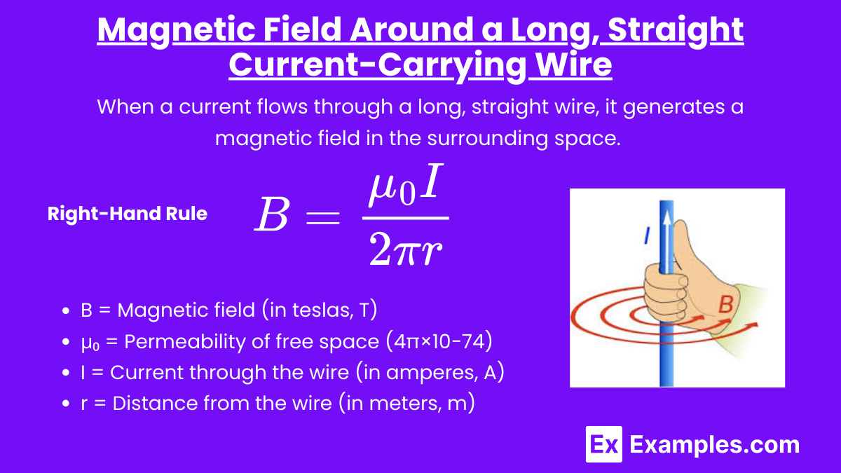
When a current flows through a long, straight wire, it generates a magnetic field in the surrounding space. This magnetic field forms concentric circles around the wire, with the wire at the center. The direction of the magnetic field can be determined using the Right-Hand Rule.
Right-Hand Rule:
Point your right thumb in the direction of the conventional current (from positive to negative).
Your fingers will curl in the direction of the magnetic field around the wire.
Key Formula: The magnitude of the magnetic field (B) at a distance (r) from the wire is given by Ampère's Law:
Where:
B = Magnetic field (in teslas, T)
μ₀ = Permeability of free space (4π×10−74\pi \times 10^{-7}4π×10−7 T·m/A)
I = Current through the wire (in amperes, A)
r = Distance from the wire (in meters, m)
Important Points:
The magnetic field strength decreases as the distance from the wire increases.
The magnetic field is directly proportional to the current flowing through the wire.
2. Magnetic Field of Two Parallel Current-Carrying Wires
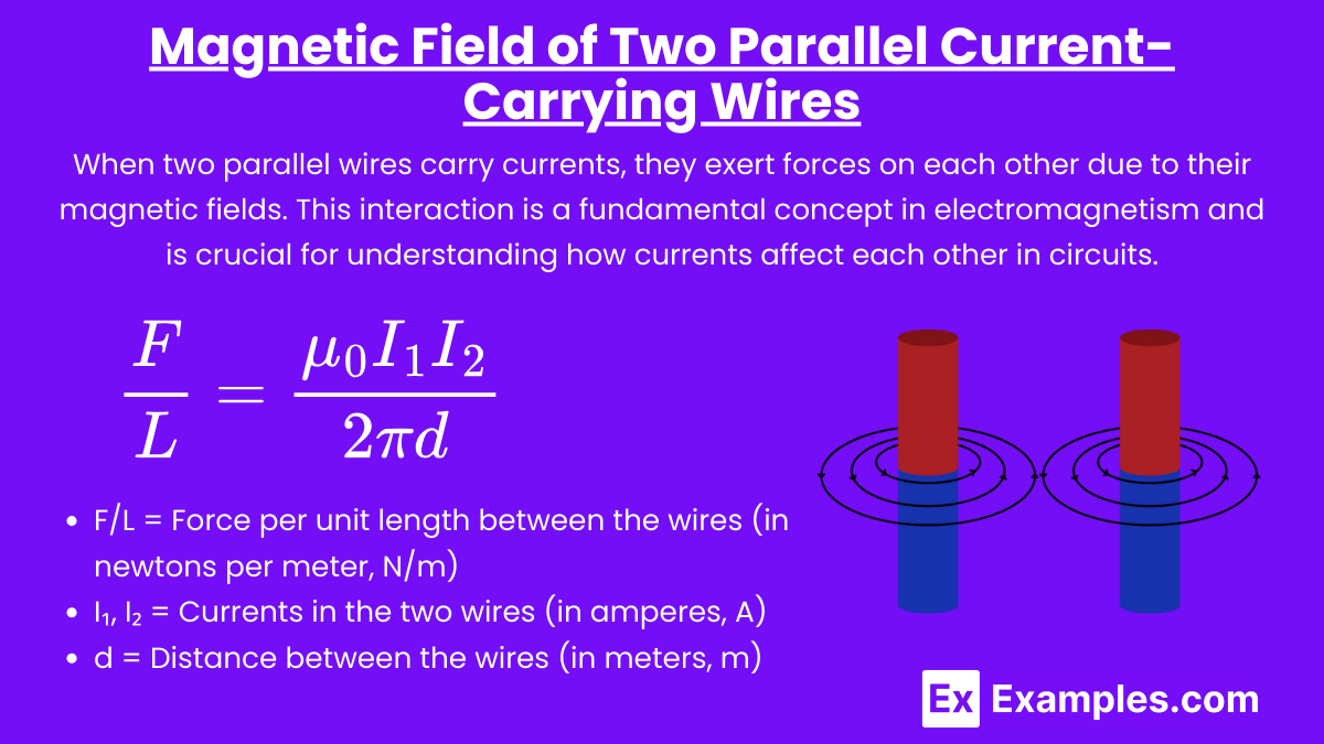
When two parallel wires carry currents, they exert forces on each other due to their magnetic fields. This interaction is a fundamental concept in electromagnetism and is crucial for understanding how currents affect each other in circuits.
Case 1: Currents in the Same Direction
Attraction: If the currents in the two wires flow in the same direction, the wires attract each other.
Magnetic Field: The magnetic fields generated by each wire add up in the region between the wires and cancel out outside, leading to a stronger field between them.
Case 2: Currents in Opposite Directions
Repulsion: If the currents flow in opposite directions, the wires repel each other.
Magnetic Field: The magnetic fields generated by each wire oppose each other between the wires and reinforce each other outside, leading to a weaker field between them.
Force per Unit Length: The force per unit length (F/L) between two parallel wires separated by a distance (d) is given by:
Where:
F/L = Force per unit length between the wires (in newtons per meter, N/m)
I₁, I₂ = Currents in the two wires (in amperes, A)
d = Distance between the wires (in meters, m)
3. Magnetic Field Inside a Solenoid
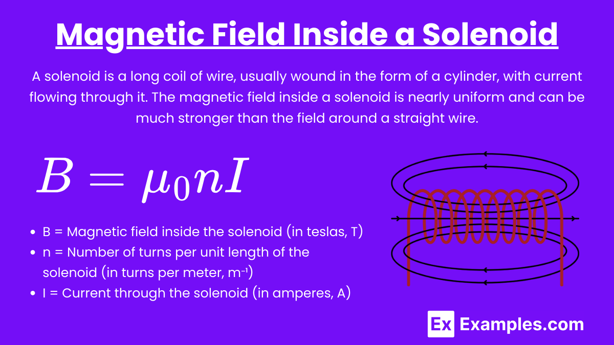
A solenoid is a long coil of wire, usually wound in the form of a cylinder, with current flowing through it. The magnetic field inside a solenoid is nearly uniform and can be much stronger than the field around a straight wire.
Key Features:
The magnetic field inside a solenoid is parallel to the axis of the solenoid.
The field outside the solenoid is relatively weak and can often be considered negligible.
Key Formula: The magnetic field inside a solenoid is given by:
Where:
B = Magnetic field inside the solenoid (in teslas, T)
n = Number of turns per unit length of the solenoid (in turns per meter, m⁻¹)
I = Current through the solenoid (in amperes, A)
Important Points:
The magnetic field strength inside the solenoid increases with the number of turns per unit length and the current.
The direction of the magnetic field can be determined using the Right-Hand Rule, similar to a single wire.
4. Application of Ampère’s Law
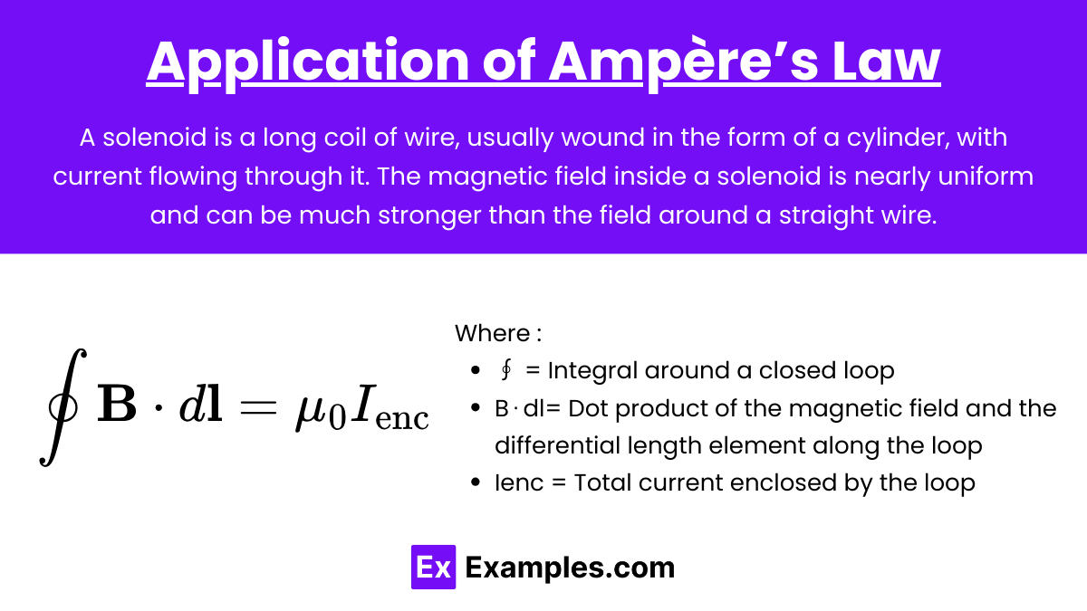
Ampère’s Law is a fundamental principle used to calculate the magnetic field in various situations involving symmetrical current distributions.
Ampère’s Law Statement: The line integral of the magnetic field (B) around a closed loop is equal to the product of the permeability of free space (μ₀) and the total current (I) passing through the loop:
Where:
∮ = Integral around a closed loop
B⋅dl= Dot product of the magnetic field and the differential length element along the loop
Ienc = Total current enclosed by the loop
Application:
For a long straight wire, Ampère’s Law can be used to derive the expression for the magnetic field, as shown earlier.
It can also be applied to solenoids and toroids, where the symmetry simplifies the calculation of the magnetic field.
5. Conceptual Understanding and Problem-Solving Tips
Visualization: Always visualize the magnetic field lines when analyzing a problem. The field lines around a wire are circular, and the density of the lines indicates the strength of the magnetic field.
Superposition Principle: If multiple wires are involved, use the superposition principle to determine the net magnetic field. Calculate the field due to each wire separately, then add the fields vectorially.
Direction and Magnitude: Pay close attention to the direction of the magnetic fields and currents. The right-hand rule is crucial for correctly determining the direction of the magnetic field.
Practice Problems: Work through problems involving varying current directions, distances, and configurations (e.g., loops, solenoids). Understanding the interplay between current, distance, and field strength is key to mastering this topic.
Examples
Here are five examples of fields generated by long current-carrying wires:
Example 1: Magnetic Field around a Single Long Straight Wire
When a current flows through a long, straight wire, it generates a magnetic field that circles the wire. The strength of this field decreases with distance from the wire and is described by Ampère's Law. This principle is used in many practical applications, such as in electromagnetic relays and in the operation of magnetic sensors.
Example 2: Magnetic Field between Two Parallel Current-Carrying Wires
When two long wires carrying currents are placed parallel to each other, they generate magnetic fields that interact. If the currents flow in the same direction, the wires attract each other; if the currents flow in opposite directions, the wires repel each other. This interaction is a fundamental concept in understanding the forces in electrical circuits and in designing power transmission systems.
Example 3: Magnetic Field in a Solenoid
A solenoid is a long coil of wire through which current flows, creating a magnetic field similar to that of a bar magnet. The field inside the solenoid is strong and uniform, while the field outside is much weaker. Solenoids are widely used in electromechanical devices, such as motors, transformers, and magnetic resonance imaging (MRI) machines.
Example 4: Magnetic Field around a Toroidal Coil
A toroidal coil is a wire wound into a circular ring shape. When current flows through the coil, it generates a magnetic field confined within the ring, creating a nearly closed-loop field. This configuration is often used in transformers and inductors because it minimizes the external magnetic field, reducing energy loss and electromagnetic interference
Example 5: Magnetic Field of a Current-Carrying Wire in a Magnetic Field
When a current-carrying wire is placed in an external magnetic field, the two fields interact, leading to a force on the wire known as the Lorentz force. This phenomenon is the basis for the operation of electric motors, where the interaction between the current in the motor windings and the magnetic field produces rotational motion.
Multiple Choice Questions
Question 1
Which of the following expressions correctly represents the magnetic field B at a distance r from a long, straight wire carrying a current I?
A)
B)
C)
D)
Answer: A)
Explanation: The magnetic field BBB around a long, straight current-carrying wire is given by Ampère's Law, specifically:
where:
B is the magnetic field,
μ0 is the permeability of free space (4π×10−7 T⋅m/A)
I is the current through the wire,
r is the radial distance from the wire.
This formula shows that the magnetic field is directly proportional to the current III and inversely proportional to the distance rrr from the wire.
Question 2
What is the direction of the magnetic field created by a long, straight current-carrying wire when the current flows vertically upwards?
A) Radially outwards from the wire
B) Radially inwards towards the wire
C) Circular and counterclockwise when viewed from above
D) Circular and clockwise when viewed from above
Answer: C) Circular and counterclockwise when viewed from above
Explanation: The direction of the magnetic field around a long, straight wire is determined by the Right-Hand Rule. If you point your thumb in the direction of the current (in this case, upwards), your curled fingers show the direction of the magnetic field. For a current flowing vertically upwards, the magnetic field circles around the wire in a counterclockwise direction when viewed from above. Hence, the correct answer is C.
Question 3
Two long, parallel wires carry currents in the same direction. What is the nature of the force between these two wires?
A) They attract each other.
B) They repel each other.
C) There is no force between them.
D) They experience a torque.
Answer: A) They attract each other.
Explanation: When two parallel wires carry currents in the same direction, they create magnetic fields that interact. According to Ampère's Law and the Biot-Savart Law, the magnetic field generated by each wire exerts a force on the other wire. If the currents are in the same direction, the magnetic fields reinforce each other between the wires, resulting in an attractive force. This attractive force is given by:
where:
I1and I2 are the currents in the wires,
d is the distance between the wires,
L is the length of the wires.
This force draws the wires together, hence the correct answer is A.