Share :
)
Inductance (including LR circuits)


 is the rate of change of current in amperes per second (A/s).

 is the rate of change of current in the primary coil.


Inductance, a fundamental concept in electromagnetism, describes how a conductor opposes changes in current flow through the creation of a magnetic field. In AP Physics, understanding inductance and its role in LR circuits is crucial. LR circuits, which consist of inductors and resistors, demonstrate transient behaviors of current growth and decay. Mastering these concepts is essential for analyzing and solving problems related to electromagnetic induction and its practical applications in various electrical systems.
Free AP Physics C: Electricity and Magnetism Practice Test
Learning Objectives
In the topic of inductance and LR circuits for the AP Physics exam, you should understand the definition and significance of inductance, both self and mutual. Learn how to calculate induced EMF using Faraday’s Law, analyze the energy stored in inductors, and solve differential equations governing LR circuits. Comprehend the time constant, and the current growth and decay in series and parallel LR circuits. Familiarize yourself with practical applications such as transformers, motors, and inductive sensors.
Inductance and LR Circuits
Inductance
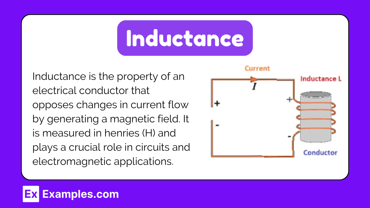
Inductance is a property of an electrical conductor that opposes changes in current. It is caused by the magnetic field generated by the current flowing through the conductor. The unit of inductance is the henry (H).
Definition
Inductance (L) is defined as the ratio of the induced electromotive force (EMF) to the rate of change of current in the circuit:
where:
L is the inductance in henries (H),
ε is the induced EMF in volts (V),
is the rate of change of current in amperes per second (A/s).
Self-Inductance
When the changing current in a coil induces an EMF in the same coil, it is called self-inductance. The induced EMF opposes the change in current according to Lenz's Law.
Formula
The induced EMF (ε) in a coil with self-inductance L is given by:
Mutual Inductance
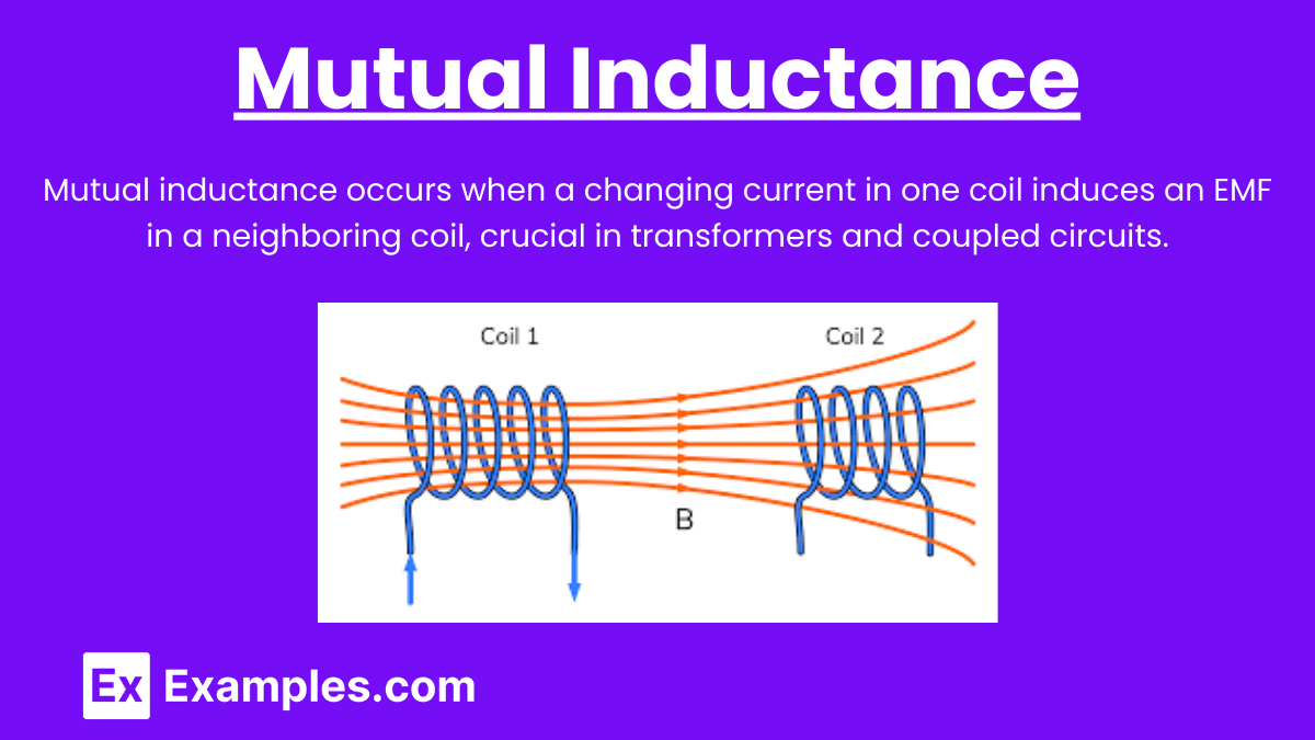
When a changing current in one coil induces an EMF in a neighboring coil, it is called mutual inductance.
Formula
The induced EMF (εεε) in the secondary coil due to the primary coil is given by:
where:
M is the mutual inductance in henries (H),
is the rate of change of current in the primary coil.
Energy Stored in an Inductor

An inductor stores energy in its magnetic field when current flows through it. The energy (EEE) stored in an inductor is given by:
LR Circuits
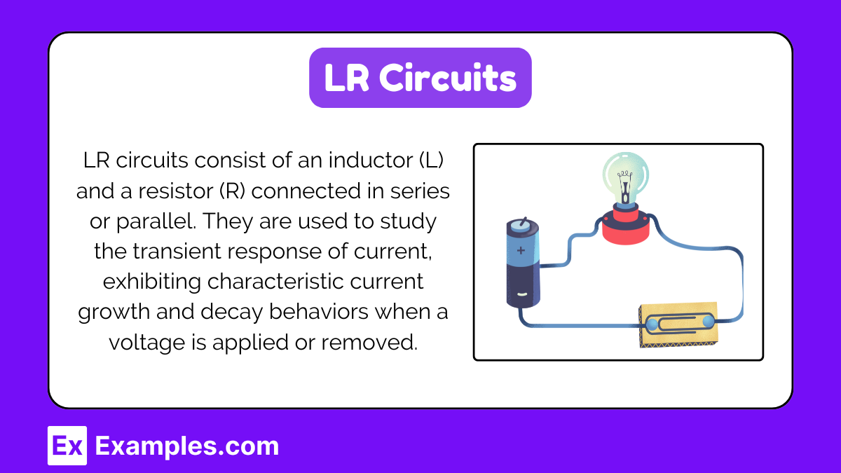
An LR circuit consists of an inductor (L) and a resistor (R) connected in series or parallel. These circuits are used to study the transient response of inductors to changes in current.
Series LR Circuit
In a series LR circuit, the inductor and resistor are connected in a single loop with a power source.
Differential Equation
The governing differential equation for a series LR circuit is:
where:
V is the applied voltage,
I is the current at time ttt,
R is the resistance.
Time Constant
The time constant (τ) of a series LR circuit is:
Current Growth
When a constant voltage V is applied to an LR circuit, the current grows according to:
Current Decay
When the voltage is removed, the current decays as:
where I0 is the initial current.
Parallel LR Circuit
In a parallel LR circuit, the inductor and resistor are connected in parallel across a power source.
Practical Examples of Inductance
Transformers
Transformers rely on mutual inductance to transfer electrical energy between two coils. They are used to step up or step down voltage levels in power distribution.
Motors and Generators
Inductance is crucial in the functioning of motors and generators. It helps in converting electrical energy to mechanical energy and vice versa.
Inductive Sensors
Inductive sensors use the principle of inductance to detect metallic objects. They are commonly used in industrial applications for position sensing.
Examples of Inductance and LR Circuits
Transformer Operation
Transformers use mutual inductance between two coils to step up or step down AC voltage in power distribution systems.
DC Motor
The inductance of the motor windings affects the current response when voltage is applied, impacting the motor’s startup behavior.
Relay Coils
Relays use inductive coils to create a magnetic field that moves a switch, controlled by the transient current response in the LR circuit.
Power Supply Filters
LR circuits in power supplies help smooth out voltage fluctuations by filtering high-frequency noise through inductive reactance.
Inductive Proximity Sensors
These sensors detect metal objects by measuring changes in inductance, used in various industrial applications for position sensing.
Practice Test Questions On Inductance and LR Circuits
What happens to the current in an LR circuit immediately after a switch is closed?
A) It jumps to its maximum value instantly.
B) It remains zero and then gradually increases.
C) It gradually increases towards a maximum value.
D) It decreases first and then increases.
Answer: C) It gradually increases towards a maximum value.
Explanation: In an LR circuit, when the switch is first closed, the inductor initially opposes changes in current due to its inductance. This results in the current starting at zero and gradually increasing to its maximum value determined by the voltage and resistance in the circuit.
Which of the following describes the role of an inductor in a circuit?
A) It stores energy in an electric field.B) It resists changes in current.C) It converts electrical energy to mechanical energy.D) It resists changes in voltage.
Answer: B) It resists changes in current.
Explanation: An inductor stores energy in a magnetic field and resists changes in current flowing through it. This property is due to the magnetic field created around the coil of the inductor, which opposes the change in current according to Lenz's Law.
What is the time constant of an LR circuit indicative of?
A) The total resistance in the circuit.B) The rate at which the current reaches its maximum value.C) The maximum voltage in the circuit.D) The power dissipated in the resistor.
Answer: B) The rate at which the current reaches its maximum value.
Explanation: The time constant (τττ) of an LR circuit is a measure of how quickly the current changes in the circuit. It is determined by the ratio of inductance (L) to resistance (R) and indicates the time it takes for the current to reach approximately 63% of its maximum value after a change in voltage is applied.