Steady-state direct-current circuits with batteries and resistors are a foundational topic in AP Physics. These circuits involve a constant flow of current, where voltages and currents reach a stable condition over time. Understanding how to analyze these circuits using Ohm’s Law and Kirchhoff’s Laws is crucial for solving complex problems. In AP Physics, mastering the behavior of resistors in series and parallel, along with calculating power dissipation, is essential for achieving high scores on the exam.
Learning Objectives
By studying Steady-state Direct-Current Circuits with Batteries and Resistors Only for the AP Physics exam, you should learn to apply Ohm’s Law and Kirchhoff’s Laws to analyze circuit behavior. You should master calculating equivalent resistance in series and parallel networks, determine current and voltage in complex circuits, and understand power dissipation in resistors. Additionally, you should develop problem-solving skills to simplify circuits and confidently approach circuit analysis questions, ensuring a strong foundation for more advanced electrical concepts.
Steady-State Direct-Current Circuits
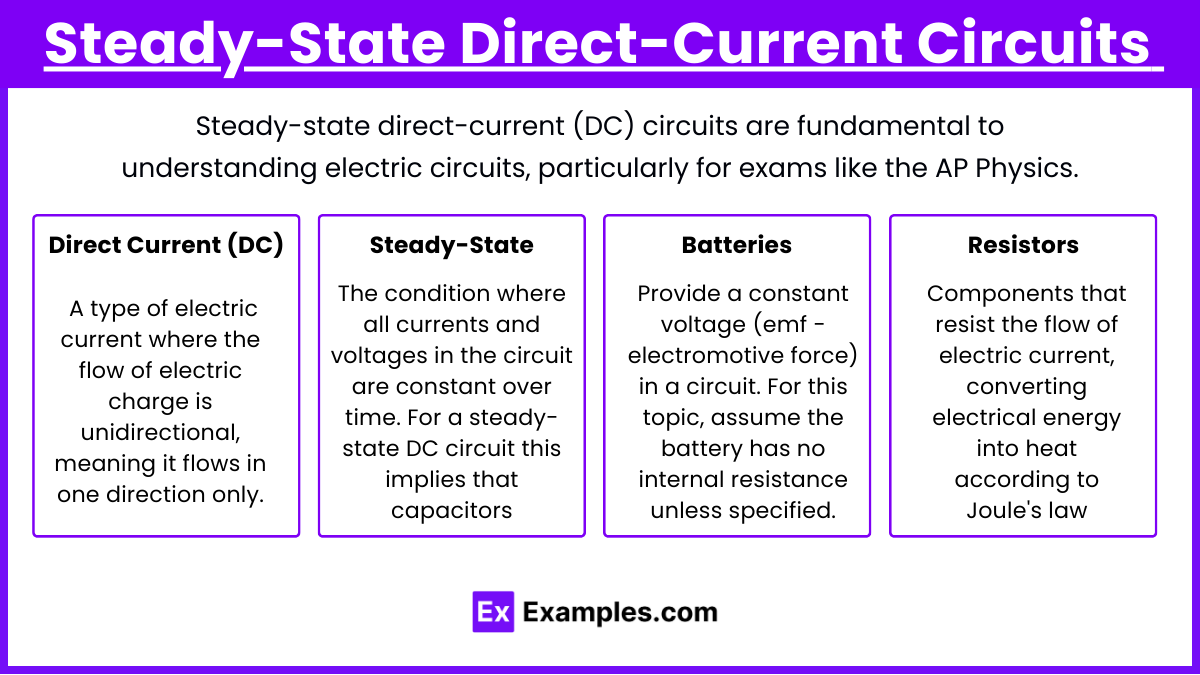
Steady-state direct-current (DC) circuits are fundamental to understanding electric circuits, particularly for exams like the AP Physics. In these circuits, steady-state means that all the currents and voltages remain constant over time. This condition occurs when all transient effects (like charging a capacitor) have settled down, and the circuit reaches a stable operation.
1. Basic Concepts
- Direct Current (DC): A type of electric current where the flow of electric charge is unidirectional, meaning it flows in one direction only.
- Steady-State: The condition where all currents and voltages in the circuit are constant over time. For a steady-state DC circuit, this implies that capacitors (if any) are fully charged and there is no change in current or voltage.
- Batteries: Provide a constant voltage (emf – electromotive force) in a circuit. For this topic, assume the battery has no internal resistance unless specified.
- Resistors: Components that resist the flow of electric current, converting electrical energy into heat according to Joule’s law.
2. Ohm’s Law
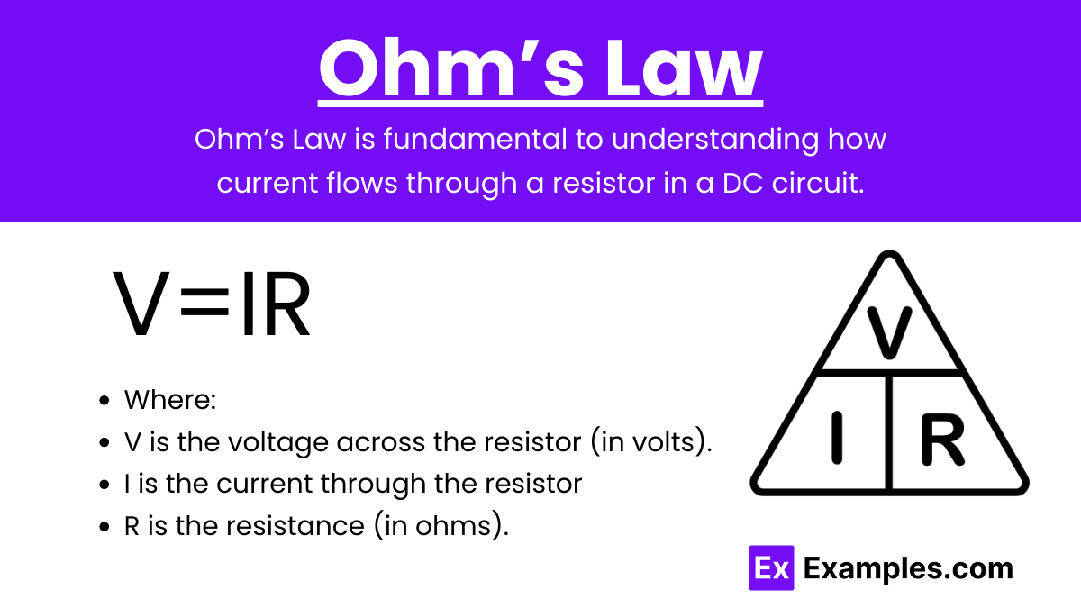
Ohm’s Law is fundamental to understanding how current flows through a resistor in a DC circuit.
V=IR
Where:
- V is the voltage across the resistor (in volts).
- I is the current through the resistor (in amperes).
- R is the resistance (in ohms).
3. Kirchhoff’s Laws
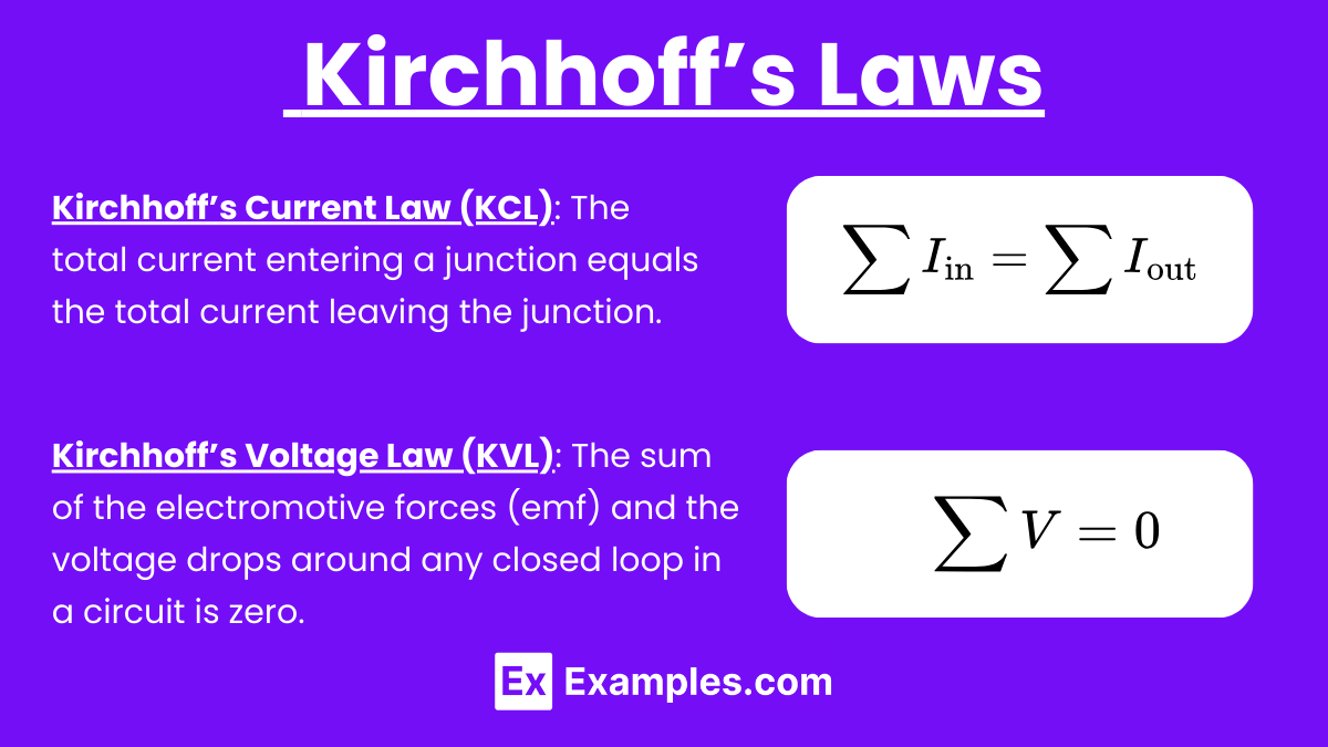
To analyze complex circuits, we use Kirchhoff’s Laws:
- Kirchhoff’s Current Law (KCL): The sum of currents entering a junction equals the sum of currents leaving the junction.
- Kirchhoff’s Voltage Law (KVL): The sum of the voltage gains and drops around any closed loop in a circuit is zero.
4. Series and Parallel Resistor Networks
Understanding how resistors combine in series and parallel is crucial for analyzing DC circuits.
- Resistors in Series: The equivalent resistance Req is the sum of individual resistances.
In a series circuit:
- The current III through each resistor is the same.
- The voltage across each resistor can be different, and the total voltage is the sum of the voltages across all resistors.
- Resistors in Parallel: The reciprocal of the equivalent resistance is the sum of the reciprocals of the individual resistances.
In a parallel circuit:
- The voltage V across each resistor is the same.
- The current through each resistor can be different, and the total current is the sum of the currents through all resistors.
5. Power in DC Circuits
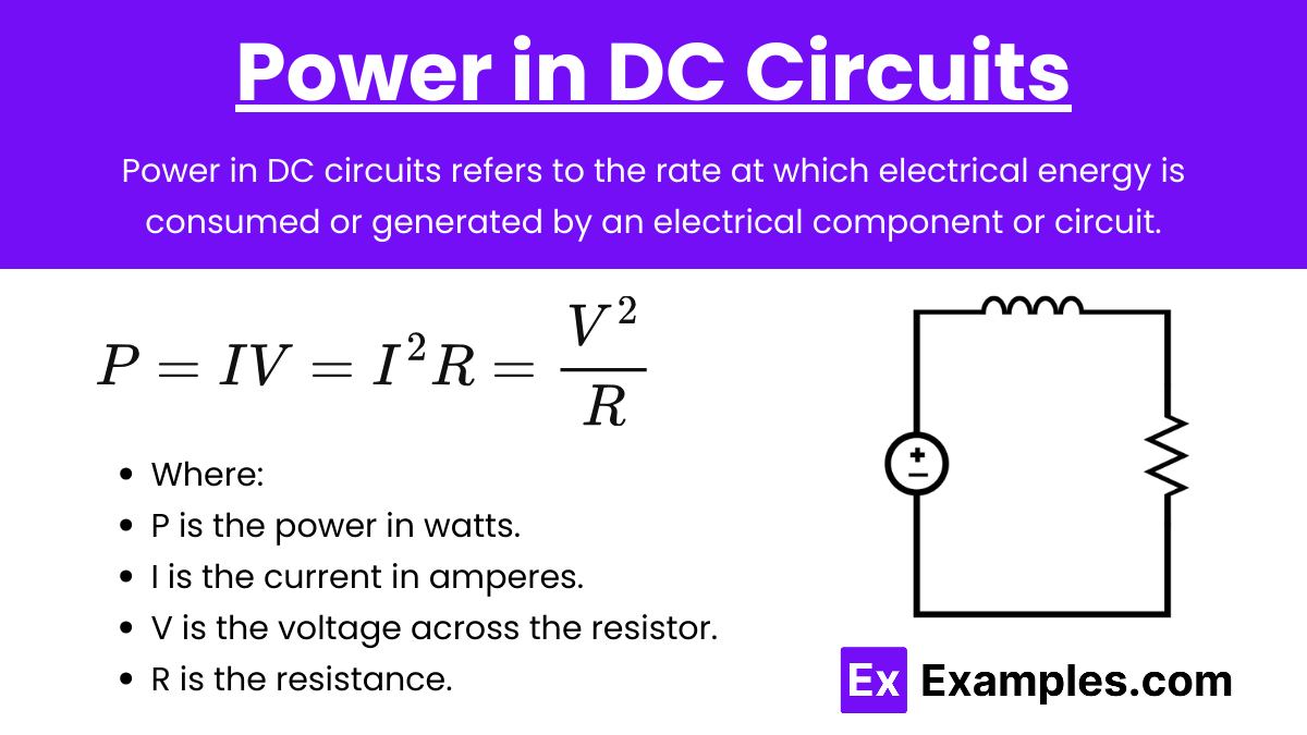
Power in DC circuits refers to the rate at which electrical energy is consumed or generated by an electrical component or circuit. In a direct current (DC) circuit, where the current flows in one direction and remains constant over time, power can be calculated using several basic formulas depending on the known quantities.
Power dissipated in a resistor is given by:
Where:
- P is the power in watts.
- I is the current in amperes.
- V is the voltage across the resistor.
- R is the resistance.
This formula helps determine how much energy is converted to heat in a resistor.
6. Analyzing Complex Circuits
When dealing with more complex circuits, such as those with multiple resistors in series and parallel, follow these steps:
- Simplify the Circuit: Combine series and parallel resistors to reduce the circuit to a simpler equivalent circuit.
- Apply Kirchhoff’s Laws: Use KCL to solve for currents at junctions and KVL to solve for voltages around loops.
- Calculate Unknowns: Use Ohm’s Law and power formulas to calculate any unknown voltages, currents, or resistances.
Examples
Here are five examples of steady-state direct-current (DC) circuits that involve only batteries and resistors:
Example 1: Series Circuit with a Single Battery and Multiple Resistors
In this circuit, a single battery is connected in series with several resistors. The total resistance is the sum of all the resistors, and the current flowing through the circuit is the same across all components. The voltage drops across each resistor are different and are determined by Ohm’s Law (V=IR).
Example 2: Parallel Circuit with a Single Battery and Multiple Resistors
This circuit features a single battery connected to multiple resistors arranged in parallel. Each resistor has the same voltage across it, equal to the battery’s voltage. However, the current through each resistor is different, depending on the resistance value, and the total current is the sum of the currents through each parallel branch.
Example 3: Series-Parallel Circuit
This circuit is a combination of both series and parallel arrangements. A battery is connected to two or more resistors in parallel, and this parallel combination is then connected in series with another resistor. The current flowing through the series part of the circuit is the same, while the voltage across the parallel resistors is the same. The overall current and voltage drops depend on both the series and parallel components.
Example 4: Voltage Divider Circuit
In this type of circuit, a battery is connected to two resistors in series. The voltage across each resistor is a fraction of the total battery voltage, depending on the resistance values. This setup is commonly used to obtain a specific voltage lower than the battery voltage at a particular point in the circuit.
Example 5: Current Divider Circuit
In this circuit, a battery is connected to two resistors in parallel. The total current from the battery splits between the parallel resistors. The current through each resistor is inversely proportional to its resistance, meaning that the resistor with lower resistance carries a higher current and vice versa.
Multiple Choice Questions
Question 1
In a simple series circuit containing a battery and three resistors (R1, R2, and R3), how does the current through each resistor compare?
A) The current through each resistor is the same.
B) The current is highest through R1 and decreases through R2 and R3.
C) The current is different through each resistor depending on their resistance values.
D) The current through each resistor is inversely proportional to their resistance.
Answer: A) The current through each resistor is the same.
Explanation:
In a series circuit, the same current flows through all components because there is only one path for the current to follow. Even though the resistors have different resistance values, the current remains constant throughout the circuit. The voltage drop across each resistor will differ depending on their resistance values, but the current will remain the same.
Question 2
Consider a parallel circuit with a battery and two resistors, R1 and R2. If R1 has a lower resistance than R2, which of the following statements is true about the current through the resistors?
A) The current through R1 is greater than the current through R2.
B) The current through R1 is equal to the current through R2.
C) The current through R1 is less than the current through R2.
D) The current through both resistors is zero because they are in parallel.
Answer: A) The current through R1 is greater than the current through R2.
Explanation:
In a parallel circuit, the voltage across each resistor is the same. However, the current through each resistor depends on its resistance according to Ohm’s Law (I = V/R). Since R1 has a lower resistance than R2, the current through R1 will be greater. This is because the same voltage across a smaller resistance results in a larger current.
Question 3
A circuit consists of a battery of voltage V and two resistors, R1 and R2, connected in series. If the voltage drop across R1 is V1 and across R2 is V2, which of the following statements is true?
A) V1=V2 because the resistors are in series.
B) V1+V2=V because the total voltage across the resistors must equal the battery voltage.
C) V1>V2 because current prefers to flow through R1.
D) V1<V2 because R2 is farther from the battery.
Answer: B) V1+V2=V because the total voltage across the resistors must equal the battery voltage.
Explanation:
In a series circuit, the sum of the voltage drops across each resistor must equal the total voltage supplied by the battery. This is due to Kirchhoff’s Voltage Law, which states that the sum of the electrical potential differences (voltage) around any closed circuit must be zero. Therefore, the total voltage supplied by the battery is divided among the resistors, so V1+V2=V.

