Current and resistance are fundamental concepts in physics, playing a critical role in understanding electric circuits and energy transfer. On the MCAT, you’ll explore electric current flow, resistivity, Ohm’s law, and the behavior of resistors in circuits. Understanding the relationship between voltage, current, and resistance, along with concepts like series and parallel circuits, is crucial, as these topics are key to mastering the physics and physical science sections of the exam.
Learning Objectives
In studying "Current and Resistance" for the MCAT, you should learn to define electric current as the flow of charge and understand the relationship between current, voltage, and resistance using Ohm’s law. Explore how resistivity and material properties affect resistance, including the impact of temperature on conductors and insulators. Understand the differences between series and parallel circuits, focusing on how current, voltage, and resistance behave in each configuration. Analyze the role of resistors in regulating current and power dissipation in circuits. Evaluate biological applications, such as nerve impulses and electrical signaling in the heart. Additionally, develop problem-solving skills for circuit-based MCAT questions by applying circuit rules and calculations effectively.
Defining Electric Current
Electric Current is defined as the rate at which electric charge flows past a point in a circuit. It is the movement of electrons or other charge carriers, such as ions, through a conducting medium, which can be a metal wire, an electrolyte, or even a semiconductor.
Mathematical Representation
The mathematical expression for electric current (I) is: I = Q/t where:
I is the current,
Q is the electric charge measured in coulombs (C),
t is the time in seconds (s) over which the charge flows.
Direction and Convention
Conventional Current Direction: By historical convention, electric current is considered to flow from the positive terminal to the negative terminal of a power source in a circuit. This convention arises from the days before electrons were discovered, and it was assumed that the flow was carried by positive charges.
Electron Flow: In reality, in conductive metals, the actual charge carriers are electrons, which are negatively charged and move from the negative terminal to the positive terminal of the power source. Despite this, the conventional current direction is still used for most engineering and physics calculations.
Types of Electric Current:
Direct Current (DC):
The flow of electric charge is in one constant direction. DC is the type of current produced by sources such as batteries and solar cells.
Commonly used in devices that require a stable and constant voltage, such as LED lighting and electronic devices.
Alternating Current (AC):
The flow of electric charge periodically reverses direction. AC is the type of current delivered to homes and businesses via power lines.
Preferred for power distribution because it is more efficient for transporting electricity over long distances. The voltage and current can be easily increased or decreased using transformers.
Measurement
Electric current is measured using a device called an ammeter, which is typically connected in series with the circuit component whose current is to be measured, ensuring that the measured current flows through the ammeter.
Ohm’s Law: Relationship Between Current, Voltage, and Resistance
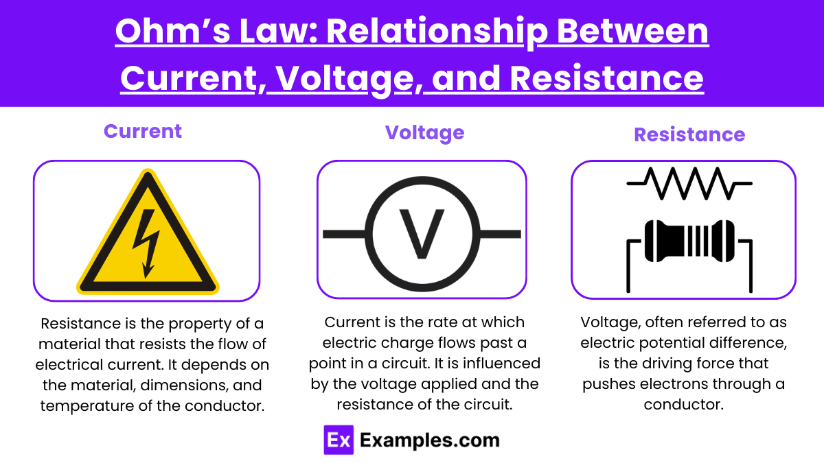
Ohm's Law states that the current through a conductor between two points is directly proportional to the voltage across the two points and inversely proportional to the resistance between them. It can be expressed mathematically as: V = IR where:
V is the voltage across the conductor (in volts, V),
I is the current flowing through the conductor (in amperes, A),
R is the resistance of the conductor (in ohms, Ω).
Components of Ohm's Law
1. Voltage (V):
Voltage, often referred to as electric potential difference, is the driving force that pushes electrons through a conductor. It is the energy per unit charge provided by an energy source, such as a battery or power supply.
2. Current (I):
Current is the rate at which electric charge flows past a point in a circuit. It is influenced by the voltage applied and the resistance of the circuit.
3. Resistance (R):
Resistance is the property of a material that resists the flow of electrical current. It depends on the material, dimensions, and temperature of the conductor. Higher resistance means less current flows for a given voltage.
Impact of Material Properties and Temperature on Resistance
Material Properties Affecting Resistance
Type of Material:
Conductors: Materials like copper, aluminum, and silver have low resistance and are commonly used in electrical wiring and components due to their high conductivity.
Insulators: Materials such as rubber, glass, and plastic have high resistance and prevent the flow of electric current, used for coating and protecting wires and devices.
Semiconductors: Materials like silicon and germanium have properties between conductors and insulators, and their resistance can be altered significantly by impurities (doping), making them fundamental in electronics.
Physical Dimensions:
Resistance is directly proportional to the length of a conductor: R∝L, where L is the length. A longer conductor provides more resistance to the flow of electric current.
Resistance is inversely proportional to the cross-sectional area of the Impact of Material Properties and Temperature on Resistance conductor: R∝1/A, where A is the area. A thicker wire has lower resistance.
Impact of Temperature on Resistance
The resistance of a material is also affected by temperature changes, which can cause the resistance to increase or decrease depending on the material type:
Conductors:
For most metallic conductors, resistance increases with an increase in temperature. When heated, the atoms in a metal vibrate more vigorously, which scatters the electrons more frequently. This scattering reduces the flow of electrons causing an increase in resistance.
The relationship between temperature and resistance in a metallic conductor can often be modeled by the equation: R(T) = R0[1+α(T−T0)] where R(T) is the resistance at temperature T, R0 is the original resistance at temperature T0, and α is the temperature coefficient of resistance for the material.
Semiconductors and Insulators:
Unlike metals, the resistance of semiconductors typically decreases as temperature increases. As temperature rises, more charge carriers (electrons and holes) are excited into the conduction band, increasing the material’s conductivity.
In certain insulating materials, increased temperature can also lead to a decrease in resistance, albeit through different mechanisms such as increased ionic conductivity.
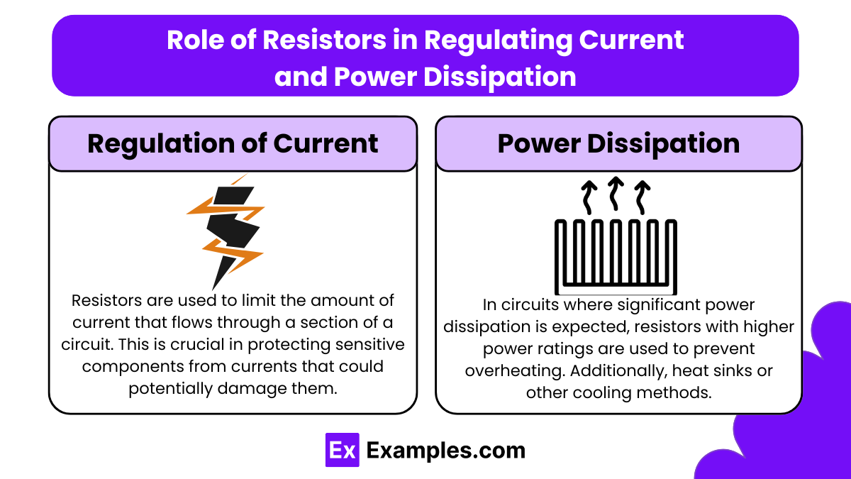
Role of Resistors in Regulating Current and Power Dissipation
Regulation of Current
Current Limiting:
Resistors are used to limit the amount of current that flows through a section of a circuit. This is crucial in protecting sensitive components from currents that could potentihttps://images.examples.com/wp-content/uploads/2024/10/Role-of-Resistors-in-Regulating-Current-and-Power-Dissipation-1.pngally damage them. For example, a resistor is often placed in series with an LED to limit the current passing through the LED to a safe level that the LED can handle without burning out.
Voltage Division:
Resistors are used in voltage divider circuits, where a voltage source is divided into two or more voltages. By arranging resistors in series and connecting a load across one of them, a portion of the input voltage can be obtained across the load, which is useful for signal conditioning and processing in electronic devices.
Power Dissipation
Heat Generation:
When current flows through a resistor, electrical energy is converted into heat energy — a phenomenon described by the power formula P = I2R or P = V2/R, where P is power, I is current, V is voltage, and R is resistance. This process is known as Joule heating or resistive heating.
The ability of a resistor to dissipate power safely is characterized by its power rating, typically expressed in watts. Exceeding this rating can lead to overheating and potential failure of the resistor.
Thermal Management:
In circuits where significant power dissipation is expected, resistors with higher power ratings are used to prevent overheating. Additionally, heat sinks or other cooling methods may be employed to manage the heat produced by these resistors.
Examples
Example 1: Household Electrical Circuits
In residential wiring, electrical appliances are connected in parallel to the power supply. This configuration ensures that each appliance receives the full voltage of the power source while allowing independent operation. For instance, if a toaster and a refrigerator are plugged into the same circuit, turning on the toaster does not affect the refrigerator’s performance. The total current drawn from the circuit depends on the resistance of each appliance and the total number of appliances in use.
Example 2: Resistors in Series
When multiple resistors are connected in series in a circuit, the total resistance increases. For example, if three resistors of equal resistance are connected in series, the total resistance is the sum of their individual resistances. This increased resistance affects the overall current flowing through the circuit. If a voltage is applied, the current is reduced compared to a single resistor, illustrating how series connections can limit the flow of electric current.
Example 3: Resistors in Parallel
In a parallel circuit configuration, multiple resistors provide alternative pathways for current to flow. For instance, if two resistors with different resistances are connected in parallel, the overall resistance of the circuit decreases. This is because the total current is the sum of the currents through each path, allowing more current to flow through the circuit than if the resistors were in series. This principle is crucial in designing circuits to ensure that devices receive adequate current.
Example 4: Ohm’s Law in Practice
Ohm's Law, which states that current is directly proportional to voltage and inversely proportional to resistance, is a fundamental principle in electronics. For example, if a battery with a voltage of 9 volts is connected to a resistor with a resistance of 3 ohms, the current flowing through the circuit can be understood using this relationship. This principle allows engineers to calculate the expected current in a circuit based on the known voltage and resistance values.
Example 5: Short Circuits
A short circuit occurs when a low-resistance path is created unintentionally, allowing excessive current to flow through the circuit. For example, if the insulation on a wire wears away and the wire touches another conductor, it creates a short circuit. This situation can lead to overheating and potential damage to electrical components or even fires. Understanding current and resistance is vital in preventing short circuits by ensuring proper insulation and using fuses or circuit breakers to limit current flow.
Practice Questions
Question 1
Which of the following statements is true regarding electric current?
A) Electric current flows from high resistance to low resistance.
B) Electric current is measured in volts.
C) Electric current is the flow of electric charge.
D) Electric current can exist in a vacuum without any medium.
Correct Answer: C) Electric current is the flow of electric charge.
Explanation: Electric current refers to the flow of electric charge, typically carried by electrons in a conductor. It is measured in amperes (A), not volts, which measure electric potential difference. Current flows from regions of higher electric potential to lower potential, and while currents can exist in certain conditions (like in a vacuum), they typically require a medium like a conductor to flow. Therefore, option C accurately defines electric current.
Question 2
What is the primary factor that determines the resistance of a conductor?
A) The length of the conductor
B) The shape of the conductor
C) The color of the conductor
D) The voltage applied across the conductor
Correct Answer: A) The length of the conductor.
Explanation: The resistance of a conductor is primarily determined by its length, cross-sectional area, and the material it is made from. Generally, longer conductors have higher resistance because electrons have to travel farther, encountering more collisions with atoms in the material. The shape and color of the conductor do not significantly impact resistance, nor does the applied voltage directly determine resistance; instead, voltage influences the current flowing through the resistance.
Question 3
In a circuit with multiple resistors, which configuration will result in a lower overall resistance?
A) Resistors connected in series
B) Resistors connected in parallel
C) Resistors connected randomly
D) Resistors not connected at all
Correct Answer: B) Resistors connected in parallel.
Explanation: When resistors are connected in parallel, the overall resistance decreases because the current has multiple paths to flow through. This configuration allows more charge to flow simultaneously, effectively reducing the total resistance. In contrast, resistors connected in series increase the total resistance because the current has only one path to take, and it must pass through each resistor sequentially. Thus, option B is correct, as it leads to a lower overall resistance in the circuit.

